Method, apparatus and system for removal of contaminants from water

a technology of water purification and water treatment, applied in water cleaning, sustainable biological treatment, biological water/sewage treatment, etc., can solve the problems of clogging or other problems, no cooling or contact at a slow enough pace to separate from the water, and now-suspended solids, so as to achieve less harmful final effluent, less volume or amount of final effluent, and less volume or volume

Inactive Publication Date: 2007-10-30
PRESBY PLASTICS INC
View PDF6 Cites 18 Cited by
  • Summary
  • Abstract
  • Description
  • Claims
  • Application Information

AI Technical Summary

Benefits of technology

[0014]An advantage of the invention is that because the system can be laid out in a number of ways, including on a slope, using one or more leaching systems, using multi-level drainage field layout, using various types of drainage / treatment conduit, and using various chemical and / or microbe treatments, the system can provide greater leaching volume in a given surface area than conventional systems and can take advantage of gravity and the slope of the land to aid in the leaching process. In addition, the nitrogen removing capability of the invention results in much cleaner, less harmful final effluent, and less volume or amount of final effluent because some of the materials and compounds that would stay in the water and / or soil if using a conventional septic system are converted to gaseous material that can vent harmlessly into the soil and air.
[0015]Another advantage of the invention is that it may be used to treat a variety of liquid waste, including, but not limited to, septic tank effluent, strong waste water having high BOD (bacterial oxygen demand—i.e. high demand on the bacteria present that are digesting the waste material), high COD (chemical oxygen demand) and suspended solids concentrations, oil contaminated water, and chemically contaminated water. The contaminated fluid is more thoroughly and completely processed by the present invention than is possible with conventional systems and can be used for example for irrigation, water recycling or further purification such as chlorination for drinking water. Thus, again while described for example for the removal of nitrogen-containing compounds the invention works very well to process and eliminate many other contaminants of waste water and thus should not be limited to nitrogen removal.
[0016]The method, apparatus and system of the invention can be easily installed, integrated and incorporated into the variety of currently-existing septic and waste treatment systems such that existing systems can be up-graded or customized to specific uses or needs, without having to be completely replaced or renovated. For example, various types of drainage / treatment conduit may be used, including, for septic purposes, any graveless system such as the SB2, Enviro-Septic®, and GEO-FLOW® brands of leaching conduit. In addition , the invention can be used with septic systems including conventional pipe and stone systems, chamber systems, and ELJEN INDRAIN® system. Also, high bacterial concentration can be used and maintained within the system. The high concentration of bacteria in the small system area possible using the present invention permits installation of small area leaching systems in small spaces where conventional septic systems could not be installed.
[0017]These and further advantages of the present invention will become apparent to those skilled in the art to which this invention pertains and after a study of the description of the invention, drawings, and the appended claims.

Problems solved by technology

The problem this causes with the septic tank is that the now-suspended solids, in passing through the tank, neither cool nor make contact at a slow enough pace to separate from the water.
Thus, the suspended solids proceed through the system and are not removed, eventually causing clogging or other problems.
Lint and fuzz has also been an on-going problem for the septic tank to control.
This material stays suspended in the septic tank liquid and normally passes through, remaining suspended in the effluent which subsequently also causes problems in the leach system connected with the septic tank.
In addition, there has always been a problem with removing harmful nitrogen containing compounds from the septic tank effluent.
To date, there is no effective way to remove these compounds.
Septic systems available to date do not effectively provide for the removal, in a manner which does not effect the cost and performance characteristics of the septic treatment system, of suspended solids, lint, fuzz, organic and human waste, and nitrogen containing compounds that are typically found in septic tank liquid.
This is partly because of the solids, lint, fuzz, nitrogen containing compounds and the like, which result in too high a BOD (bacterial oxygen demand) for the bacteria present to fully break down and digest the waste material, too high a COD (chemical oxygen demand) for any added chemicals to react with and break down the waste material and, simply too high an amount of total suspended solids present.
So far there has been no way to fully and effectively overcome these increasing problems.
A leach field, for example, is adversely effected by suspended solids because the suspended solids will clog the receiving layer and also adversely affect the absorption characteristics of the leach bed.
However, to date there is still no effective way to remove the harmful nitrogen containing compounds from septic effluent / waste water.
These compounds, such as ammonia, and various nitrates and nitrites are harmful to people, animals and the environment, and must simply be diluted and dispersed eventually in to the soil in concentrations low enough not to cause harm and to eventually be further diluted and dispersed by and in the soil.
Although others have tried, including using carbon, the methods developed to date cannot effectively remove nitrogen containing compounds even when carbon is used.
There is nothing currently available which satisfies these needs.

Method used


Image

  • Method, apparatus and system for removal of contaminants from water
  • Method, apparatus and system for removal of contaminants from water
  • Method, apparatus and system for removal of contaminants from water

Examples


Embodiment Construction

[0049]The following is a description of the preferred embodiment of the invention. It is clear that there may be variations in the size and the shape of the system, in the materials used in the construction and in the orientation of the various parts and devices of the system. However, the main features are consistent and the particular objectives, features and advantages are as disclosed herein.

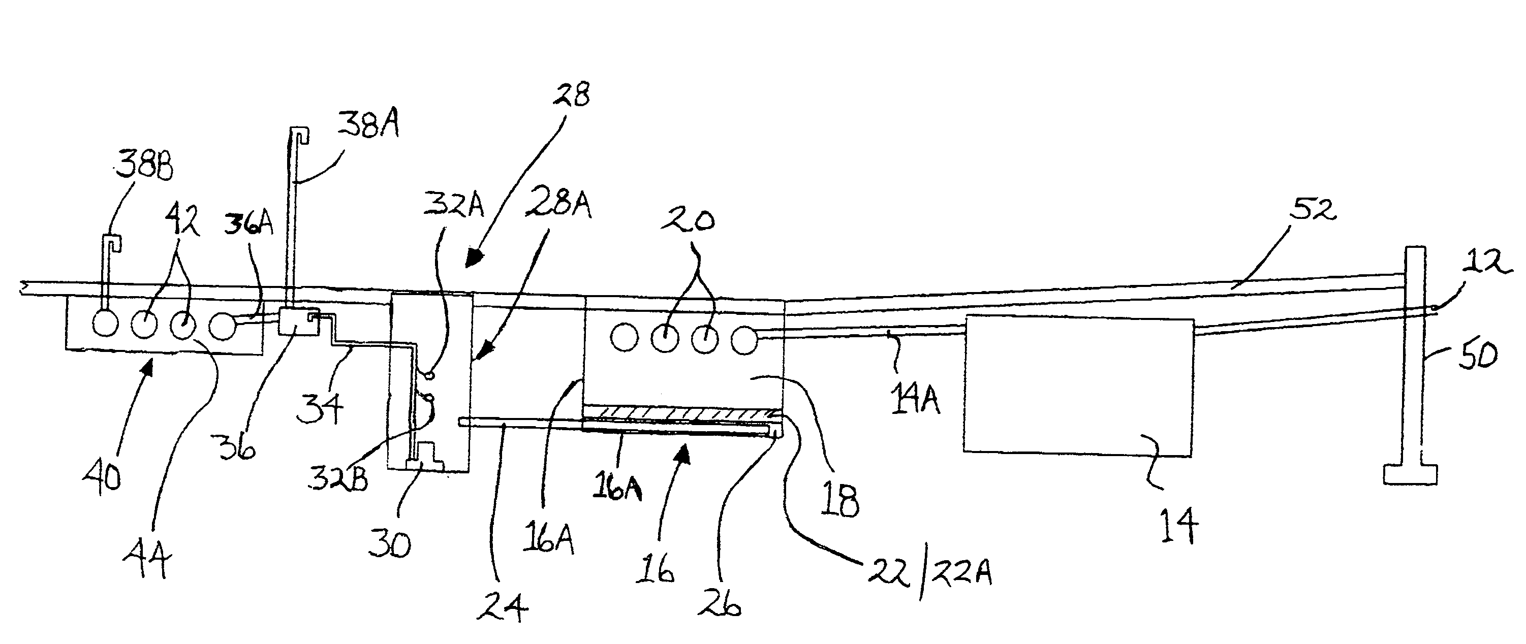
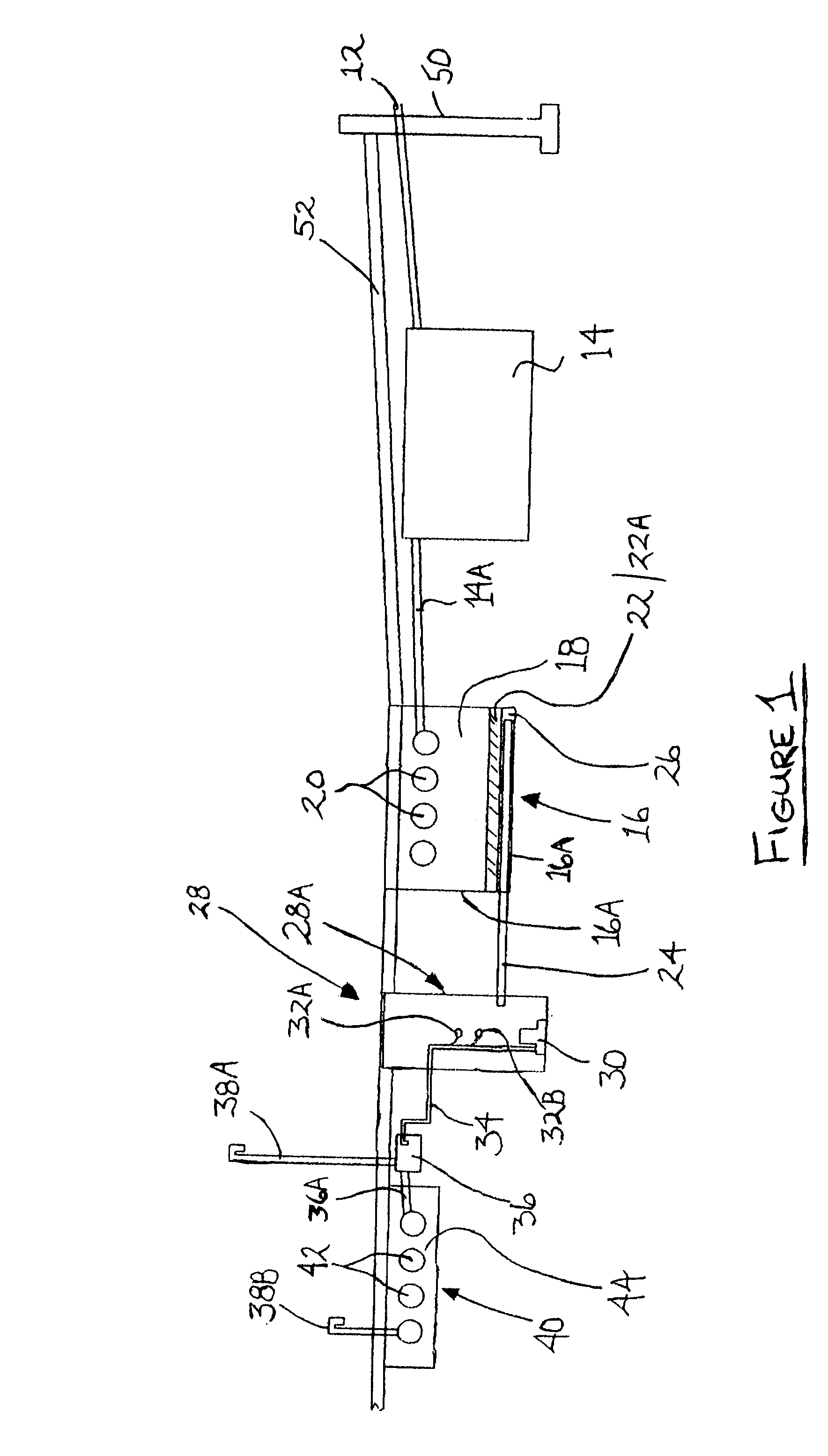
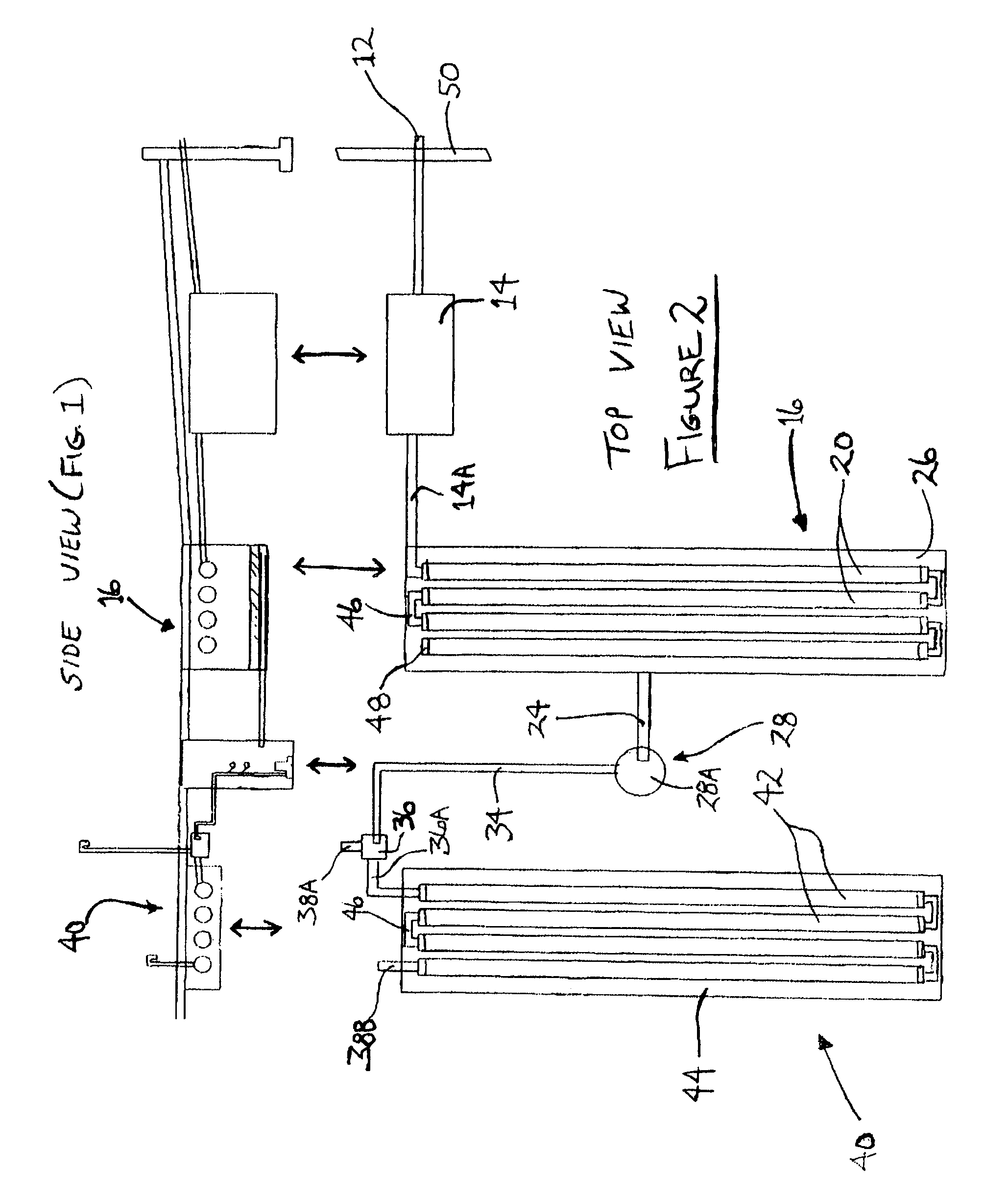
[0050]A most basic embodiment of the invention is a system for removing nitrogen and other compounds from waste fluid such as leachate comprising: a waste introduction conduit in flow communication with a septic or other waste disposal, storage or treatment tank; an aerobic condition leaching system in flow communication, via the waste introduction conduit, with the outlet from the waste tank; a carbon source in which anaerobic / anoxic conditions can be created; means for creating and maintaining anaerobic conditions and means for exit from the carbon source material and anaerobic conditions ...


PUM

PropertyMeasurementUnit
heightaaaaaaaaaa
lengthaaaaaaaaaa
lengthaaaaaaaaaa

Abstract

Disclosed is a water de-contamination system, methods, and apparatus using alternating aerobic, anaerobic, and aerobic conditions, with carbon and other waste processing treatments, to remove contaminants from water. Included is an aerobic system in flow communication with an outlet from a waste tank; waste processing treatments in flow communication with liquid exiting the aerobic system and in which anaerobic conditions can be created; means for creating and maintaining anaerobic conditions either within the waste processing treatments or after fluid exits the waste processing treatments; means for return of the fluid into aerobic conditions. A fluid retaining device within which anaerobic conditions are maintained and nitrogen-containing compounds and other contaminants are processed and removed is used. Waste processing treatments are provided within or adjacent the fluid retaining device. Included are outflow means for fluid to exit the fluid retaining device and enter aerobic conditions for final processing and release.

Description

RELATED APPLICATIONS[0001]This application claims priority under 35 USC § 120 to prior U.S. Provisional Application No. 60 / 497,248 to the same Applicant, filed 22 Aug. 2003, titled Method, Apparatus and System for Removal of Nitrogen Compounds from Leaching Systems. This application also claims priority under 35 USC § 120 to U.S. Provisional Application No. 60 / 507,926 to the same Applicant, filed 1 Oct. 2003, titled Method, Apparatus and System for Removal of Nitrogen Compounds from Leaching Systems.GOVERNMENT GRANTS / SUPPORT[0002]NoneBACKGROUND AND FIELD OF THE INVENTION[0003]The invention relates to systems for processing liquid waste, particularly septic or leaching system waste. More particularly the invention relates to methods, apparatuses and systems for removing nitrogen-containing and other compounds such as phosphorus and suspended solids from waste water such as that in septic systems. The system includes, in part, a process of alternating aerobic, anaerobic, and aerobic c...

Claims


Application Information

Patent Timeline
Patent Type & Authority Patents(United States)
IPC IPC(8): C02F3/00C02FC02F3/30
CPCC02F3/288C02F3/302C02F1/008C02F3/301C02F2003/003C02F2305/06C02F2103/002C02F2103/005C02F2103/06C02F2209/40C02F2209/42C02F2101/16Y02W10/10
Inventor PRESBY, DAVID W.
Owner PRESBY PLASTICS INC
Why Eureka
Try Eureka