
Process and apparatus for the thermal treatment of pulverulent substances

a technology of thermal treatment and pulverizing substances, which is applied in the direction of physical/chemical process catalysts, calcination, metal/metal-oxide/metal-hydroxide catalysts, etc., can solve the problems of pulverulent substance caking, coarse lumps, and long treatment time, and achieve the effect of safe handling

Inactive Publication Date: 2007-10-30
UMICORE AG & CO KG
View PDF24 Cites 30 Cited by
  • Summary
  • Abstract
  • Description
  • Claims
  • Application Information

AI Technical Summary

Benefits of technology

[0049]The pulverulent substance may be cooled and / or specially passivated under an inert atmosphere so that it can be safely handled.

Problems solved by technology

Known heat treatment methods for pulverulent substances take place in batch processes and therefore require long treatment times and are difficult to automate.
Moreover, a disadvantage with these known furnace heat treatment processes, in which the material being heat treated is introduced into the furnace in dishes, pans or other containers, is the formation of agglomerations, coarse lumps and caking of the pulverulent substances as well as the occurrence of inhomogeneities that are caused by a non-uniform heat treatment due to temperature gradients in the furnace chamber, as well as by variable gas accessibility depending on the position in the furnace chamber.
Known revolving tubular furnaces have considerable disadvantages in terms of energy consumption due to the large dead volume.
Furthermore the material being heat treated is contaminated by parts of the tubing and adhering catalyst residues.
This process cannot be used for supported catalysts containing noble metals.
A disadvantage of the flame-heated reactor system is an irregular temperature / time profile as well as the necessity to feed in fuel gases and air, or oxygen, to produce the flame.
As a result, the system is disadvantageously complex.
On account of the high density the powder mist is inhomogeneous however, with the result that particle-particle contact and thus agglomerations occur during the heat treatment.
The decomposition of the silver salt on the carrier material is however incomplete, with the result that an additional heating step is necessary in order to activate the catalyst.
Although this process leads to alloyed noble metal catalysts, it is very complicated and expensive.
The disadvantage of these thermal treatments (calcination) is that, on account of the thermal stress of the material, the metal crystallites applied to the carrier become mobile and sinter.
A thermal treatment of pulverulent catalysts at high temperatures without such sintering effects with simultaneous alloy formation, fixing of the metal on the support, and decomposition of metal oxides or the removal of surface functionalities is not possible according to the prior art.
A disadvantage of this process is that it includes a further complicated step involving the production of metal-containing, pulverulent catalysts.

Method used


Image

  • Process and apparatus for the thermal treatment of pulverulent substances
  • Process and apparatus for the thermal treatment of pulverulent substances

Examples


Embodiment Construction

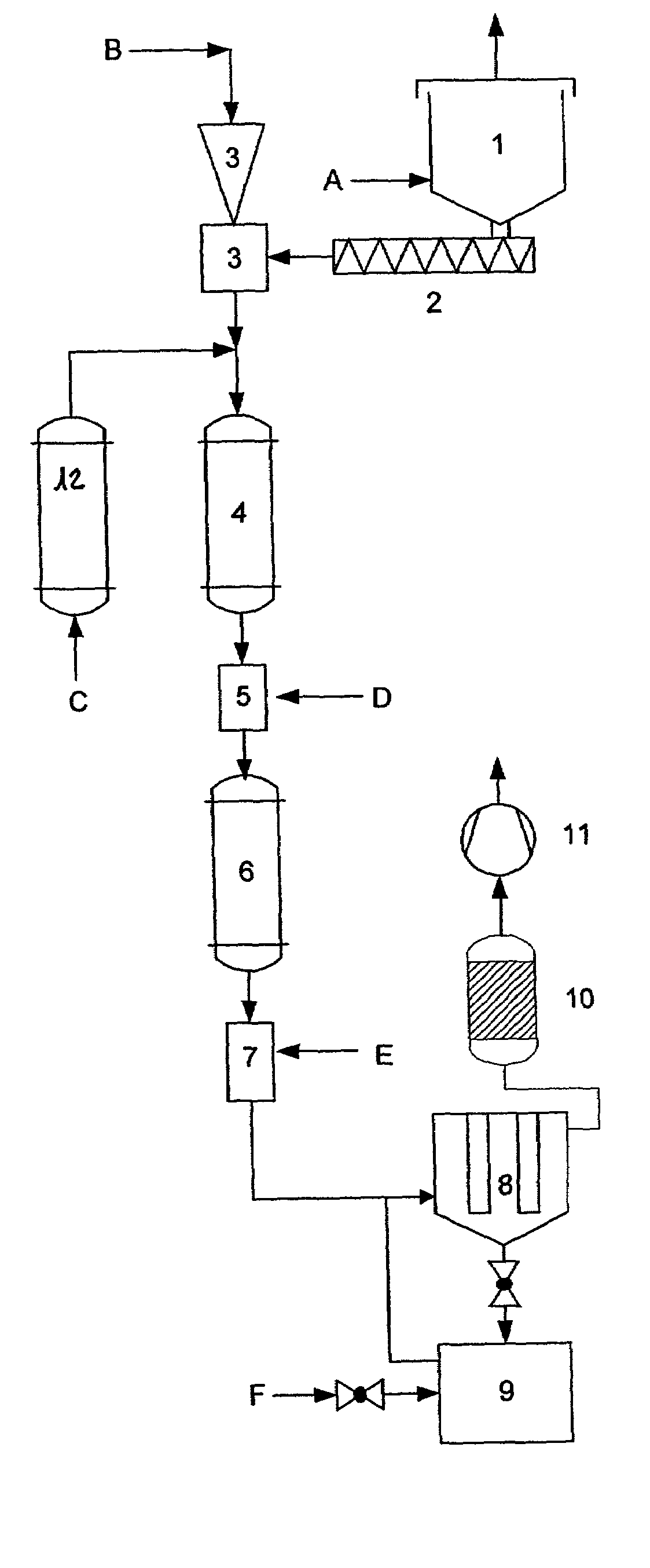
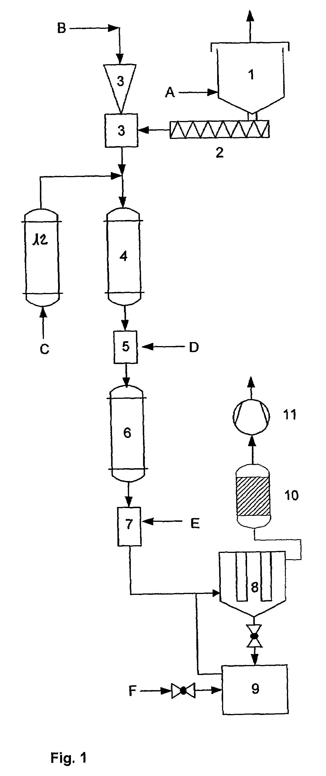
[0053]This apparatus is characterised in that it comprises a storage container (1), a conveying screw (2) that together with a carrier system forms metering scales that are connected to an injector unit (3), the injector unit (3) being arranged at the upper end of a reaction section (4 to 7), and the reaction section (4 to 7) consisting of a heating zone (4), a conditioning unit (5), a second heating zone (6) and a quenching section (7).

[0054]Carrier gas may be fed into the reaction section (4 to 7) via a carrier gas preheating section (12).

[0055]The product is separated by means of a filter (8) and a product collecting vessel (9). The carrier gas is then scrubbed by means of the gas washer (10), the transportation and pressure in the device being regulated by means of the valve (11).

[0056]The process according to the invention as well as the apparatus according to the invention are described and illustrated in more detail with the aid of FIG. 1.

[0057]According to FIG. 1, the pulver...


PUM

PropertyMeasurementUnit
Temperatureaaaaaaaaaa
Sizeaaaaaaaaaa
Energyaaaaaaaaaa

Abstract

Process and apparatus for the thermal treatment of pulverulent substances, in which the pulverulent substance is dispersed in a carrier gas and is passed in a continuous manner through a heated reactor where it is thermally treated and is then quenched by a cooling medium and is collected in a gas-solids separating unit.

Description

BACKGROUND OF THE INVENTION[0001]1. Field of the Invention[0002]The invention relates to a process and an apparatus for the thermal treatment of pulverulent substances.[0003]2. Description of Related Art[0004]Known heat treatment methods for pulverulent substances take place in batch processes and therefore require long treatment times and are difficult to automate. Moreover, a disadvantage with these known furnace heat treatment processes, in which the material being heat treated is introduced into the furnace in dishes, pans or other containers, is the formation of agglomerations, coarse lumps and caking of the pulverulent substances as well as the occurrence of inhomogeneities that are caused by a non-uniform heat treatment due to temperature gradients in the furnace chamber, as well as by variable gas accessibility depending on the position in the furnace chamber.[0005]Known revolving tubular furnaces have considerable disadvantages in terms of energy consumption due to the larg...

Claims


Application Information

Patent Timeline
IPC IPC(8): B01J23/00B01J21/18B01J6/00B01J8/00B01J8/12B01J19/00B01J19/12B01J19/14B01J37/08B01J37/34
CPCB01J6/004B01J8/0055B01J8/006B01J8/0075B01J8/12B01J8/125B82Y30/00B01J19/14B01J37/08B01J19/126B01J23/00B01J2208/00168B01J2208/00309B01J2208/00327
Inventor AUER, EMMANUELBIBERBACH, PETERGROSS, MICHAELGUTSCH, ANDREASPRIDOHL, MARKUSRUTH, KARSTENSTAAB, EDWIN
Owner UMICORE AG & CO KG
Learn More