
Millimeter wave antenna

a millimeter wave antenna and antenna module technology, applied in the field of antennas, can solve the problems of difficult to provide the extremely tight spacing between adjacent antenna modules, the overall cost of the phased array antenna system is lower, and the space is severely limited

Active Publication Date: 2007-10-30
THE BOEING CO
View PDF5 Cites 16 Cited by
  • Summary
  • Abstract
  • Description
  • Claims
  • Application Information

AI Technical Summary

Benefits of technology

The present invention is a microwave phased array antenna system that provides a close spacing between adjacent antenna modules needed for operation at 60 GHz (i.e., within the V-band spectrum). The system includes an electromagnetic wave energy distribution panel that is mounted to one side of a mandrel and includes a waveguide splitter, power amplifiers, and applications specific integrated circuits for controlling the beam radiated from the module. The mandrel also includes a second end with a plurality of apertures into which independent antenna modules are disposed. The antenna modules are electrically coupled to the distribution panel via an interconnect assembly. The system provides an inline architecture through the use of at least one electromagnetic wave distribution panel mounted along a side portion of the mandrel and can be easily coupled together to form a single, larger antenna system with thousands of antenna modules.

Problems solved by technology

This ultimately lowers the overall phased array antenna system costs.
A drawback of the tile architecture is that space is severely limited as frequency and scanning angle increases since the electronics and input / output pads must fit within the physical area of the radiators in the array lattice.
However, even with the 3D flashcube implementation, it is difficult to provide the extremely tight antenna module spacing between adjacent antenna modules that is needed to achieve + / −60° scanning in the microwave frequency spectrum (e.g., 60 GHz).
The limitation of using the three layer flexible stripline for interconnections is that as scan angles and frequencies increase, the stripline must be bent at very, very tight (i.e., small) bend radii in order to achieve the extremely close antenna module spacing required for + / −60° scan angle performance in the microwave frequency spectrum.

Method used


Image

  • Millimeter wave antenna
  • Millimeter wave antenna
  • Millimeter wave antenna

Examples


Embodiment Construction

[0033]The following description of the preferred embodiment(s) is merely exemplary in nature and is in no way intended to limit the invention, its application, or uses.

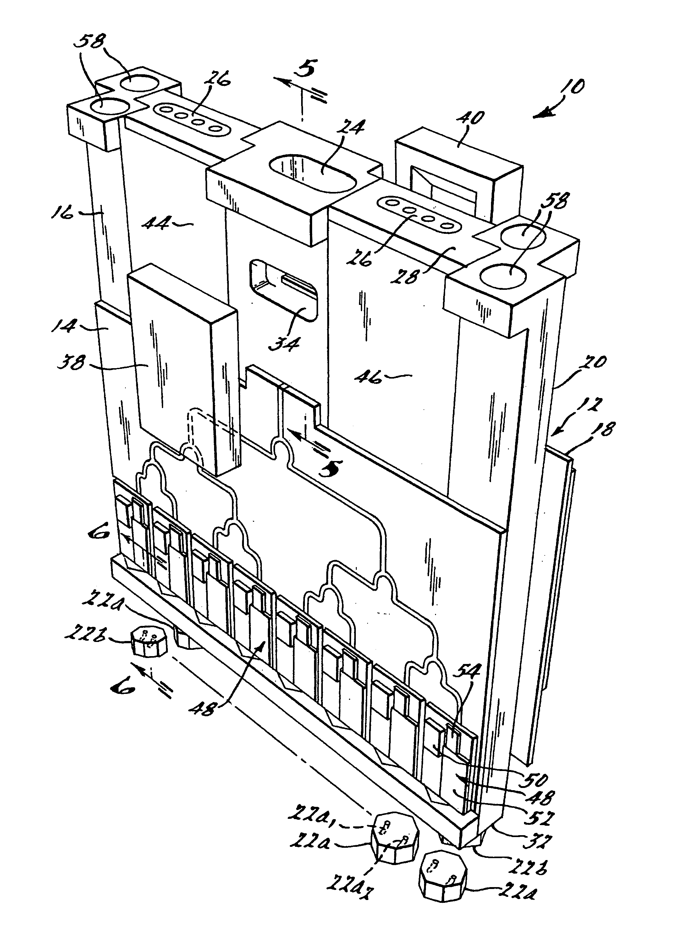
[0034]FIGS. 2 and 3 illustrate an antenna system 10 in accordance with a preferred embodiment of the present invention. The antenna system 10 is able to operate within the V-band spectrum, and more preferably at 60 GHz, with ±60° scanning capability. The system 10 generally includes a mandrel 12, a first electromagnetic wave energy distribution panel 14 secured to a first side 16 of the mandrel 12, a second electromagnetic wave energy distribution panel 18 secured to a second opposing side 20 of the mandrel 12, and a pair of subpluralities of antenna modules 22a and 22b. The mandrel 12 includes an input 24 and a pair of spaced apart interconnects 26 for coupling to a printed circuit board (not shown). The interconnects 26 and the input 24 are formed at a first end 28 of the mandrel 12 and the modules 22a and 22b are d...


PUM


Abstract

A microwave phased array antenna module. The antenna module includes a mandrel having an integrally formed waveguide splitter. Separate electromagnetic wave energy distribution panels that each include DC power, data and logic interconnects, as well as electronic modules incorporating ASICs, phase shifters and power amplifiers, are disposed on opposite sides of the mandrel. Waveguide coupling elements are further secured to the mandrel on opposing sides thereof to couple the electromagnetic wave energy received through an input port of the mandrel with each of the distribution panels. Antenna modules are disposed within openings formed in a second end of the mandrel and electrically coupled via electrical interconnects with the distribution panels. The use of the distribution panels provides ample room for the needed electronics while the use of radiating modules disposed at the second end of the mandrel in a brick-type architecture arrangement relative to distribution panels, enables the extremely tight radiating module spacing needed for V-band operation at up to + / −60° scan angles.

Description

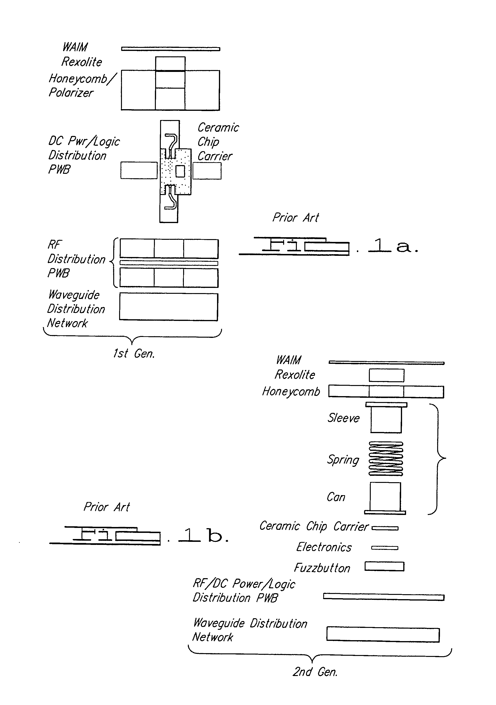
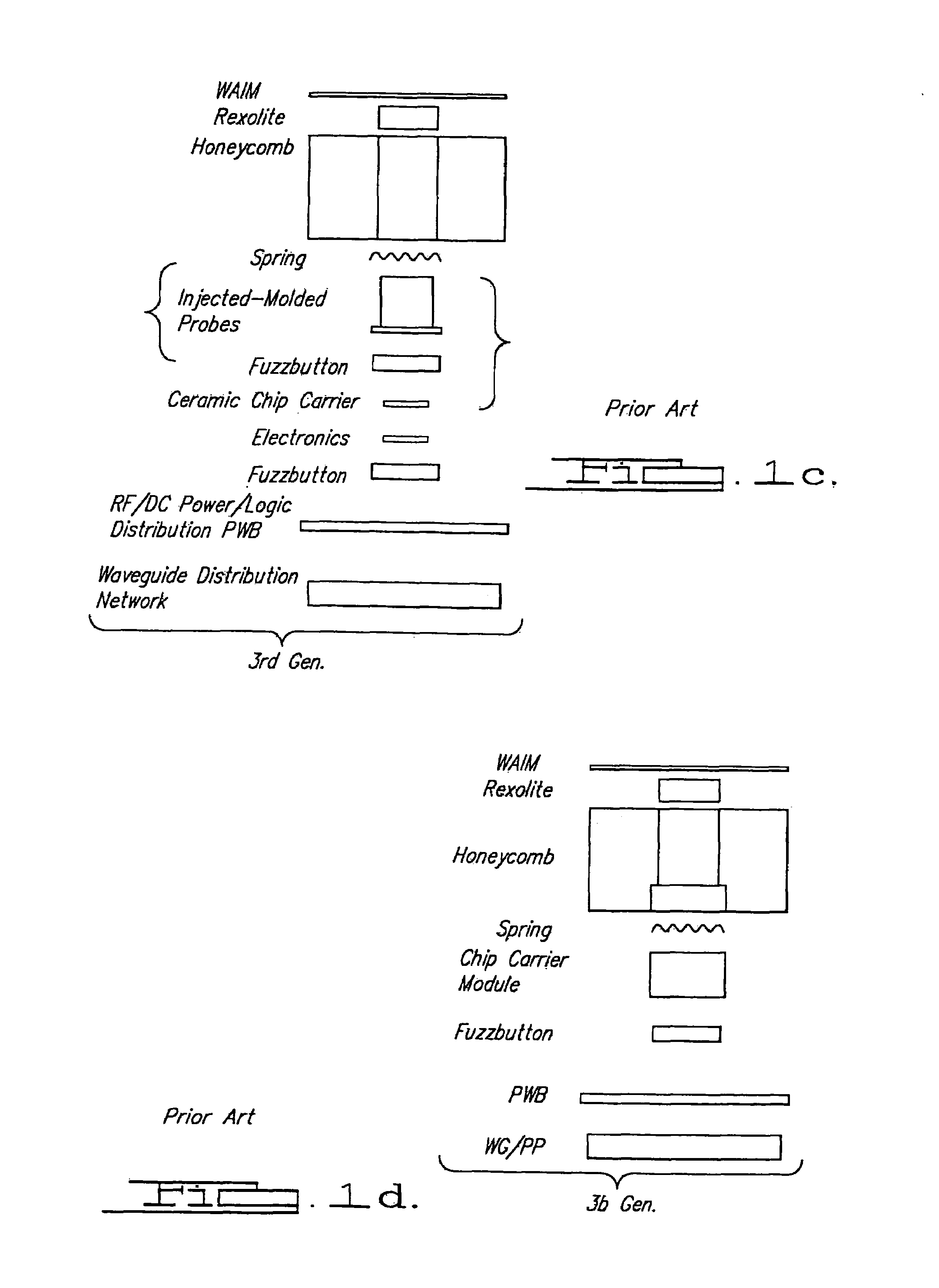
CROSS-REFERENCE TO RELATED APPLICATIONS[0001]This application claims priority from U.S. Ser. No. 60 / 532,156 filed on Dec. 23, 2003, the disclosure of which is incorporated herein by reference.FIELD OF THE INVENTION[0002]The present invention relates to antennas, and more particularly to a dual polarized, microwave frequency, phased array antenna.BACKGROUND OF THE INVENTION[0003]The Boeing Company (“Boeing”) has developed many high performance, low cost, compact phased array antenna modules. The antenna modules shown in FIGS. 1a–1c have been used in many military and commercial phased array antennas from S-band to Q-band. These modules are described in U.S. Pat. No. 5,886,671 to Riemer et. al. and U.S. Pat. No. 5,276,455 to Fitzsimmons et. al., both herein incorporated by reference.[0004]The in-line first generation module has been used in a brick-style phased-array architecture at K-band and Q-band. The approach shown in FIG. 1a requires elastomeric connectors for DC power, logic an...

Claims


Application Information

Patent Timeline
Patent Type & Authority Patents(United States)
IPC IPC(8): H01Q13/00H01Q13/02H01Q21/00
CPCH01Q21/0025H01Q13/02
Inventor NAVARRO, JULIO ANGEL
Owner THE BOEING CO
Learn More