Adaptive optics imaging system with object acquisition capability

an optical imaging system and adaptive optic technology, applied in the field of adaptive optics systems, can solve the problems of creating aberrations that are constantly changing, increasing data transmission needs, and increasing the cost and difficulty of fiber optic infrastructure additions,

Active Publication Date: 2007-10-30
EOS DEFENSE SYST USA INC
View PDF23 Cites 35 Cited by
  • Summary
  • Abstract
  • Description
  • Claims
  • Application Information

AI Technical Summary

Benefits of technology

[0009]The present invention overcomes the limitations of the prior art by providing an adaptive optics imaging system that has an acquisition imaging subsystem to assist in acquisition and alignment of the system to a target object. A wavefront sensor in the adaptive optics imaging system is aligned to a reference object in the acquisition imaging subsystem. The target object is also aligned to the reference object. In this way, alignment of the target object with the wavefront sensor is achieved.

Problems solved by technology

While the use of fiber optics has increased the capacity and efficiency of data transmission, the expanding data transmission needs require continual additions to the fiber optics infrastructure at enormous expense and difficulty.
However, the inevitable changes in atmospheric conditions are a significant impediment to the accuracy and reliability of free space optical data transmission systems.
For example, atmospheric conditions such as wind, heat waves and the like create aberrations that are constantly changing.
This, in turn, degrades the quality of the wavefront that is received, resulting in degradation of the overall quality of the data transmission.
However, for certain applications, it can be difficult to align the adaptive optics system.
However, it is generally difficult to align a receiver with a narrow field of view to a transmitted beam which is also narrow in beam width.
However, both of these solutions have significant drawbacks.
As mentioned above, increasing the width of the transmitted optical beam means that a greater percentage of the beam will not be collected by the receiver optics and will be wasted, lowering the overall efficiency of the system.
In addition, if multiple receivers are located close to one another, a transmitted optical beam that is wider than the collection aperture of the receiver optics may spill over to adjacent receivers, interfering with their proper operation.
In addition to collecting more background noise, increasing the field of view increases the chances that auto-tracking receivers will track the wrong object.
However, systems may sometimes begin to track the wrong object, for example the sun, glints, or other bright objects that appear within the system's field of view.
Increasing the field of view increases the risk that this might happen.

Method used


Image

  • Adaptive optics imaging system with object acquisition capability
  • Adaptive optics imaging system with object acquisition capability
  • Adaptive optics imaging system with object acquisition capability

Examples


Embodiment Construction

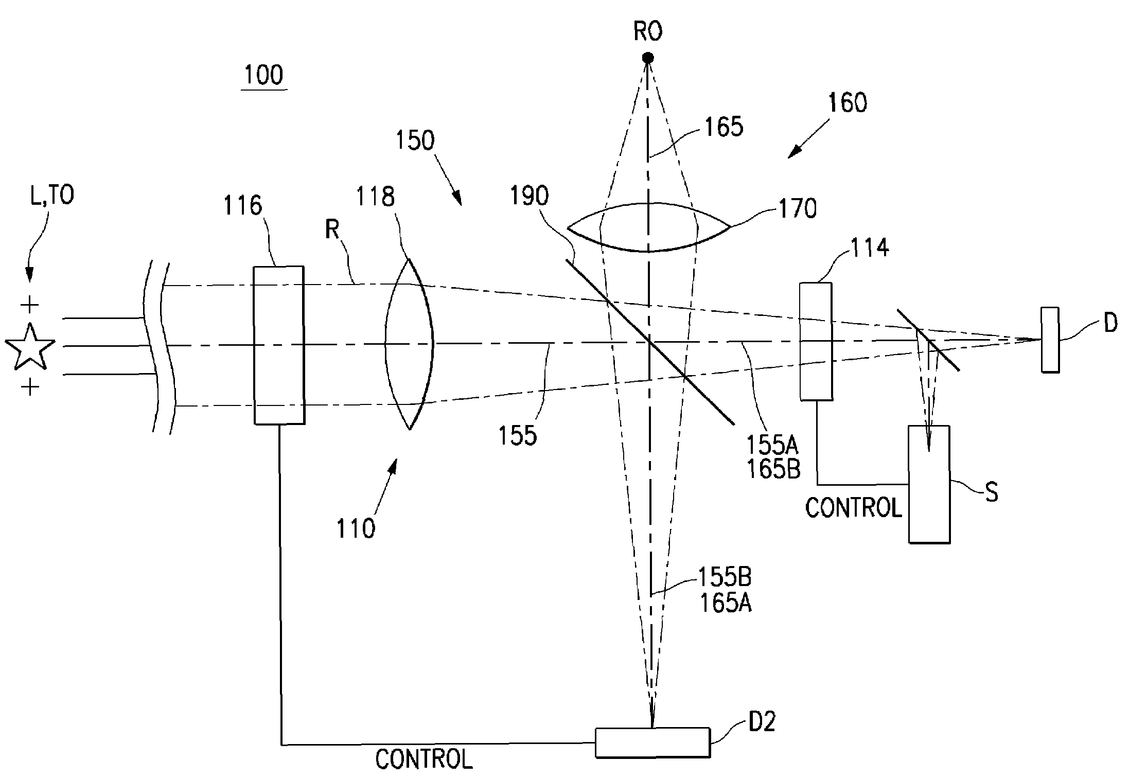
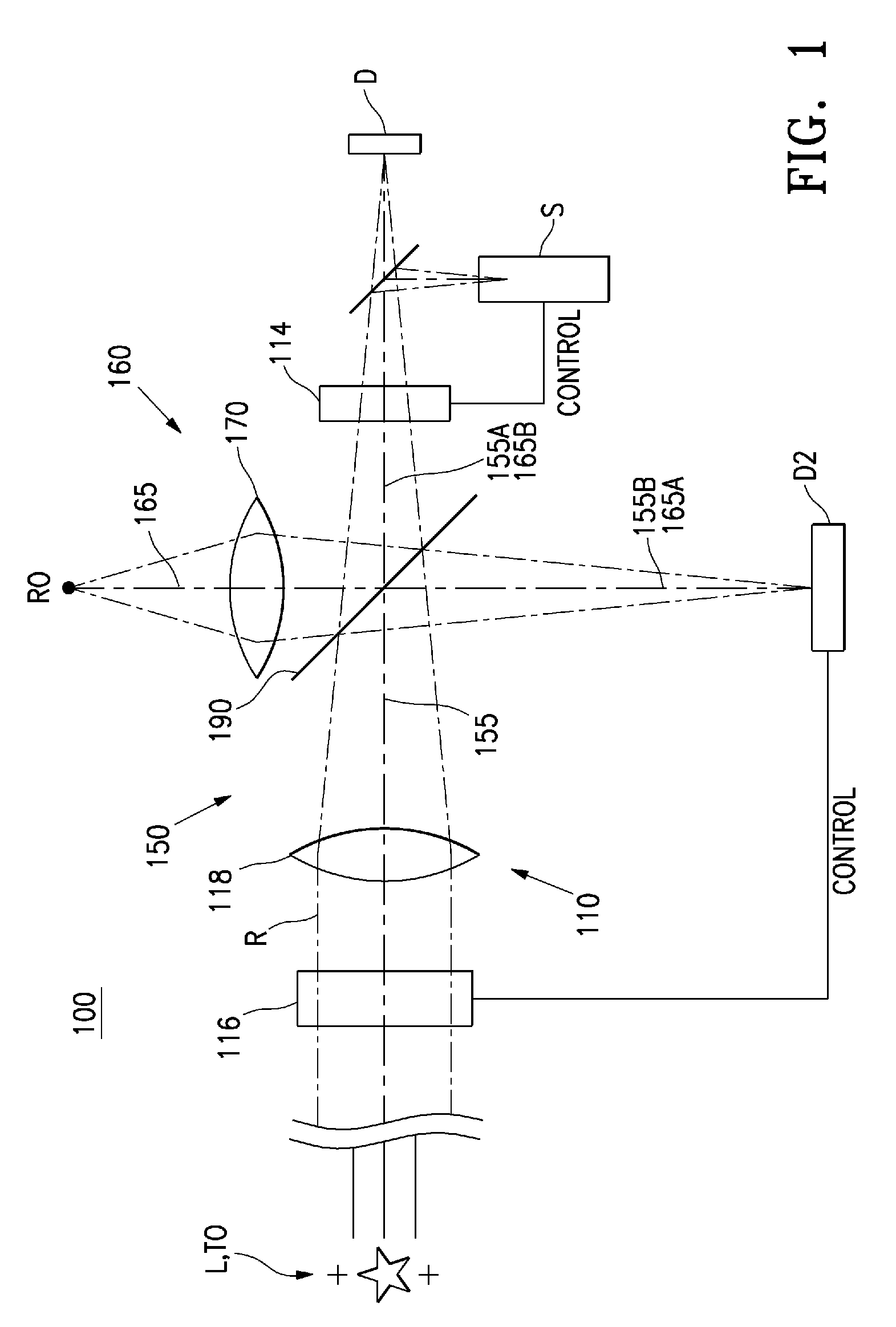
[0020]FIG. 1 is an illustration of an adaptive optics imaging system 100 according to the present invention. The system 100 includes a primary imaging subsystem 150 and an acquisition imaging subsystem 160, which are located in fixed positions relative to each other. The system 100 also include a beamsplitter 190 that combines the two imaging subsystems 150 and 160, as will be further described below.

[0021]The primary imaging subsystem 150 includes a telescope 110 (represented by lens 118 in FIG. 1), a variable phase device 114 and a wavefront sensor S. The telescope 110 has an optical axis 155. The variable phase device 114 and wavefront sensor S are located on the optical axis 155, with the wavefront sensor S downstream of the variable phase device 114. The primary imaging subsystem 150 typically also includes a detector D. In this example, a beamsplitter 126 splits the optical axis between the detector D and wavefront sensor S. The primary imaging subsystem 150 also includes a be...


PUM


Abstract

An adaptive optics imaging system has an acquisition imaging subsystem to assist in initial acquisition and alignment of the system to a target object. A wavefront sensor in the adaptive optics imaging system is aligned to a reference object in the acquisition imaging subsystem. The target object is also aligned to the reference object. In this way, alignment of the target object with the wavefront sensor is achieved.

Description

CROSS-REFERENCE TO RELATED APPLICATION[0001]This application claims priority under 35 U.S.C. § 119(e) to U.S. Provisional Patent Application Ser. No. 60 / 439,846, “Adaptive Optics Imaging System with Object Acquisition Capability,” filed Jan. 13, 2003. The subject matter of the foregoing is incorporated herein by reference in its entirety.BACKGROUND OF THE INVENTION[0002]1. Field of the Invention[0003]This invention relates generally to adaptive optics systems and, more particularly, to object acquisition and alignment of adaptive optics systems.[0004]2. Description of the Related Art[0005]With recent advances in technology, there is an increasing interest in the use of adaptive optics for various applications. For example, there is a rapidly expanding need for data transmission and an infrastructure to accomplish it. While the use of fiber optics has increased the capacity and efficiency of data transmission, the expanding data transmission needs require continual additions to the f...

Claims


Application Information

Patent Timeline
Patent Type & Authority Patents(United States)
IPC IPC(8): H04B10/00
CPCH04B10/112G02B26/06
Inventor GRAVES, J. ELON
Owner EOS DEFENSE SYST USA INC
Why Eureka
Try Eureka