Method and apparatus for delivering a high pressure gas from a cryogenic storage tank

a high-pressure gas and cryogenic storage tank technology, applied in the direction of positive displacement liquid engines, container discharging methods, machines/engines, etc., can solve the problems of high-pressure gas delivery systems, burdened by challenges, and cryogenic storage presents its own challenges, so as to reduce heat transfer and eliminate any potential failure points

Inactive Publication Date: 2007-11-13
WESTPORT FUEL SYST CANADA INC +1
View PDF32 Cites 86 Cited by
  • Summary
  • Abstract
  • Description
  • Claims
  • Application Information

AI Technical Summary

Benefits of technology

[0030]Any material in the insulation space or in the accumulator space designed to reduce heat transfer may be chosen such that it falls below 15 W / m×K. In a further embodiment, the cryogenic tank assembly may include a pump, accumulator and heater integrated together wherein the accumulator would be integrated between the pump and heater. Integrated connections between each component may help to eliminate any potential failure point.

Problems solved by technology

Substituting diesel with such gaseous fuels generally results in cost, availability and emissions benefits over diesel.
These developments, however, require such gaseous fuels to be delivered to the engine for combustion at high pressures.
Such prior art high pressure gas delivery systems, however, have been burdened by challenges arising from the need to provide a practical gas fueling system that supplies adequate on-board fuel storage while, at the same time, ensuring that the platform integrating the power generation system, be it stationary power or vehicular power, is not unduly burdened by additional equipment and / or large fuel tanks.
While, as mentioned above, there are advantages to utilizing LNG and other liquefied gases, cryogenic storage presents its own challenges.
Moreover, numerous fittings and connectors are required to join together such a fuel system each of which is a potential failure point or leak path compromising the reliability of such a system as a whole.
A similar problem arises where heating systems are used to provide pressurized gas.
These systems are also unsuitable for high pressure direct injection engines where improved efficiency and emissions can be achieved.

Method used


Image

  • Method and apparatus for delivering a high pressure gas from a cryogenic storage tank
  • Method and apparatus for delivering a high pressure gas from a cryogenic storage tank
  • Method and apparatus for delivering a high pressure gas from a cryogenic storage tank

Examples


Embodiment Construction

)

[0045]Throughout the following description specific details are set forth in order to provide a more thorough understanding of the invention. However, the invention may be practiced without these particulars. In other instances, well known elements have not been shown or described in detail to avoid unnecessarily obscuring the present invention. Accordingly, the specification and drawings are to be regarded in an illustrative, rather than a restrictive, sense.

[0046]Generally, the subject invention relates to a fuel delivery system, namely, a cryogenic tank assembly that incorporates a cryogenic tank and an integrated apparatus comprising a pump and accumulator that is for use in a cryogenic environment. A heater may also be incorporated into the apparatus downstream of the accumulator.

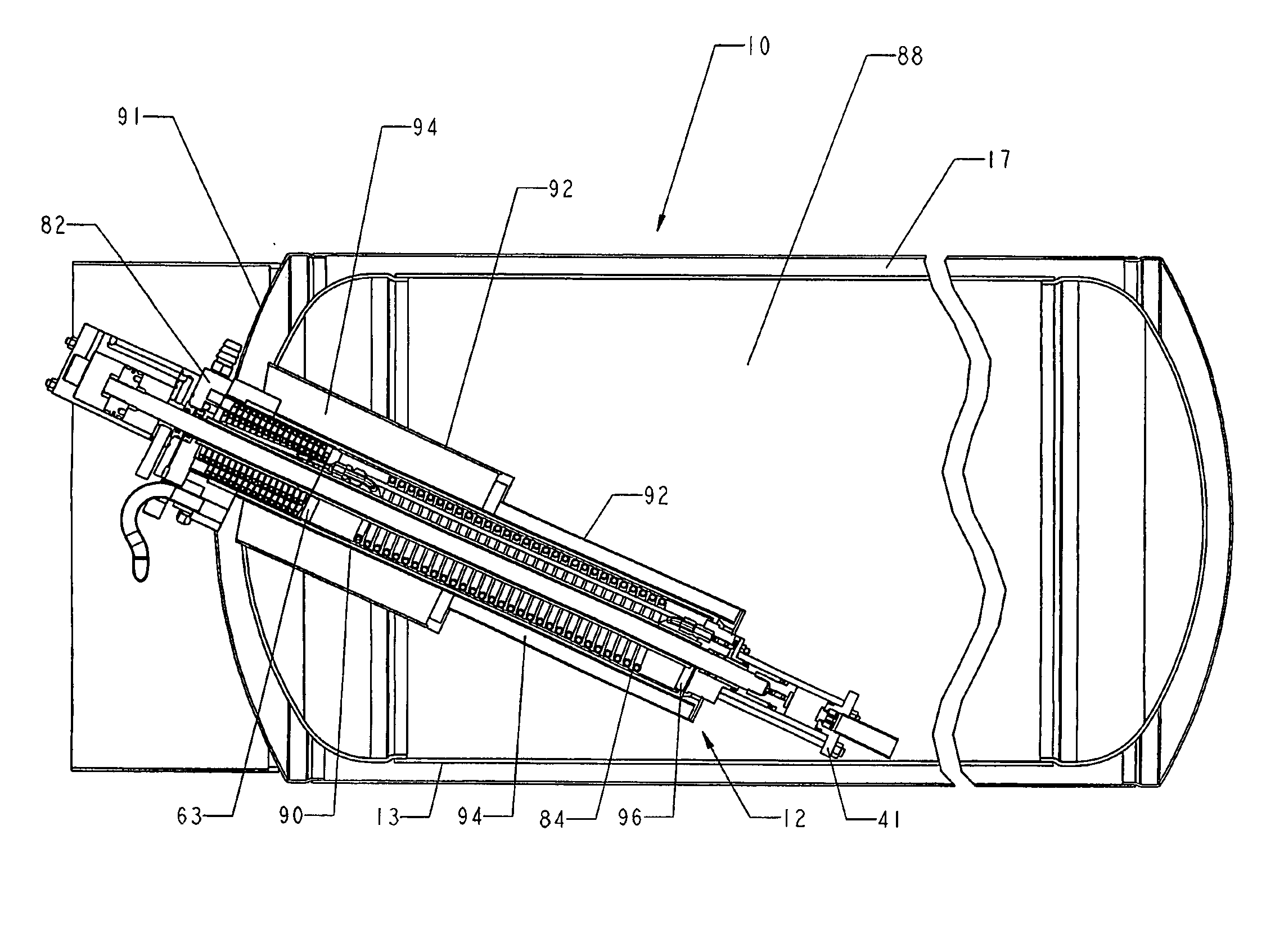
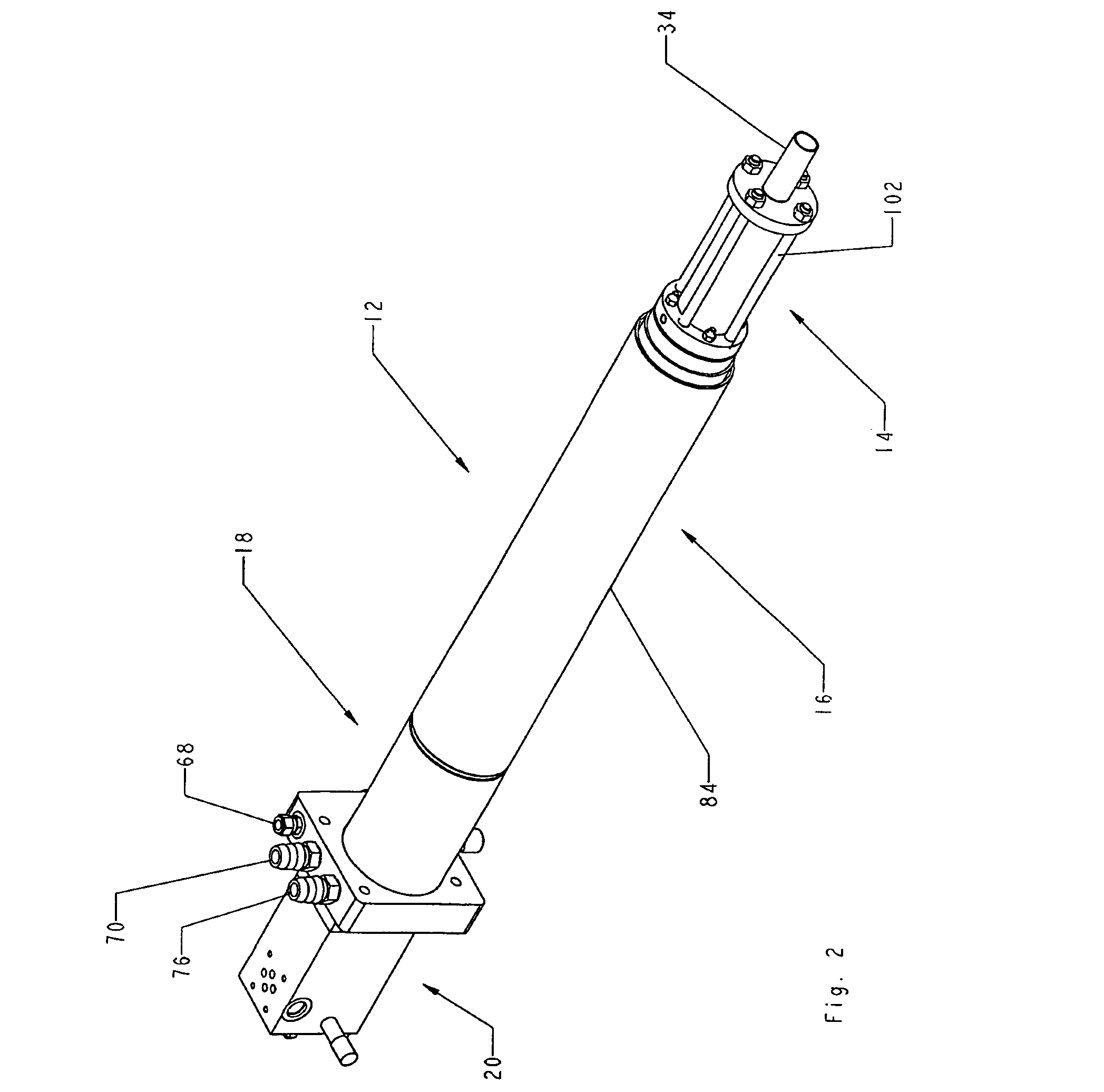
[0047]With reference to FIG. 1, cryogenic tank assembly 10 is shown with apparatus 12 incorporated for the most part within vessel 13. Referring to FIGS. 2 and 3, apparatus 12 incorporates four distin...


PUM


Abstract

A cryogenic tank assembly has a pump which discharges into an accumulator which is located in the cryogenic storage area. This reduces the space required for the device as well as the functioning of the device. The high pressure fluid in the accumulator remains at a cryogenic temperature. The system may also include a heater to deliver high pressure gas form the liquid storage volume.

Description

FIELD OF THE INVENTION[0001]This invention relates to a gas delivery system.BACKGROUND OF THE INVENTION[0002]Developments in combustion engine technology have shown that compression ignition engines, known as diesel-cycle engines, may be fueled by gaseous fuels without sacrifices in performance or efficiency. Examples of such fuels include natural gas, methane, propane, ethane, gaseous combustible hydrocarbon derivatives such as methanol and hydrogen. Substituting diesel with such gaseous fuels generally results in cost, availability and emissions benefits over diesel. These developments, however, require such gaseous fuels to be delivered to the engine for combustion at high pressures.[0003]Such prior art high pressure gas delivery systems, however, have been burdened by challenges arising from the need to provide a practical gas fueling system that supplies adequate on-board fuel storage while, at the same time, ensuring that the platform integrating the power generation system, b...

Claims


Application Information

Patent Timeline
Patent Type & Authority Patents(United States)
IPC IPC(8): F17C13/00F17C7/02F17C9/02F17C3/08F17C7/00F17C9/00F17C13/02F17C13/10
CPCF17C3/08F17C7/00F17C9/00F17C13/005F17C13/02F17C13/10Y02E60/321F17C2221/012F17C2221/033F17C2221/035F17C2223/0161F17C2227/0135F17C2221/011F02M21/0221Y02E60/32Y02T10/30F04B15/08F04B2015/081F17C9/02
Inventor NOBLE, STEPHEN D.BROOK, THOMAS C.FOLLETT, LANCE G.HARPER, GREGORY C.
Owner WESTPORT FUEL SYST CANADA INC
Why Eureka
Try Eureka