System and method for identifying upper layer protocol message boundaries

a protocol message and protocol message technology, applied in the field of system and method for identifying upper layer protocol message boundaries, can solve the problems of preventing the system from supporting 10 gigabit network traffic, incurring high overhead of processing and copying, and consuming a substantial amount of host processing power and memory bandwidth at the receiver

Active Publication Date: 2007-11-13
AVAGO TECH INT SALES PTE LTD
View PDF4 Cites 41 Cited by
  • Summary
  • Abstract
  • Description
  • Claims
  • Application Information

AI Technical Summary

Benefits of technology

[0017]In yet another embodiment, the present invention may provide a method that detects a potential error in a byte stream transport protocol segment by comparing a received error detection code with a computed error detection code over a framing PDU. The method may include one or more of the following steps: if the comparing occurs before byte stream transport protocol processing, then discarding received segment and relying on the byte stream transport recovery protocol without need for specific framing layer recovery; if the comparing occurs after the byte stream transport protocol processing, then tearing down connection; and allowing for additional protection beyond the byte stream transport checksum protocol.
[0018]In yet another embodiment, the present invention may provide a method in which no information is stored from one TCP segment to allow the processing of another TCP segment.
[0019]In yet another embodiment, the present invention may provide a method that provides additional protection of a marker by attaching, to the marker, 16 bits of error detecting code such as a cyclical redundancy checking (CRC), for example, CRC 16.
[0020]In yet another embodiment, the present invention may provide a method that allows additional information to be carried in the reserved bits (e.g., 16 reserved bits) of the Marker. For example, this can be another marker for a ULP specific purpose or any other useful data that can be carried in a sequence of these 16 bit entities. For example, the reserved field can be used for signaling between 2 ULPs.

Problems solved by technology

However, receiving, buffering, processing and storing die data communicated in TCP segments can consume a substantial amount of host processing power and memory bandwidth at the receiver.
The host CPU, which incurs high overhead of processing and copying including, for example, handling many interrupts and context switching, does this.
For an average of three data copies, the memory subsystem of most commercially available server computers becomes a bottleneck, thereby preventing the system from supporting 10 Gigabit network traffic.
A problem is that the NIC has no idea what portion of a received frame is, for example, ULP data and what portion is ULP control.
However, each ULP protocol may have its own way of mixing data and control, thereby making it very difficult to build a NIC that supports them all.
Another problem is that TCP offers a byte stream service to the ULP.
It is not always possible to tell the beginning of a ULP message (e.g., the protocol data unit (PDU)) inside that endless stream of bytes (e.g., the TCP data).
However, even if a sender could somehow be adapted to employ, in every TCP segment, a TCP layer adapted to place ULP control information starting in the first payload byte of the TCP segment, it might not be enough.
There is no guarantee the TCP segments will arrive on the other end of the wire, the way the sender has built them because, for example, there may be network architectural structures between the sender and the receiver.
This behavior by the middle box may disrupt the nicely placed control and data portions.
Thus, although the receiver may be able to order the smaller frames, the receive may be unable to locate, for example, the ULP header and the ULPDU.
Accordingly, the receiver may not be able to ascertain the control and boundary information that may be necessary to correctly place the ULPDU in the proper location of, for example, the application buffer of the receiver.
Another problem is that TCP / IP networks may deliver segments out of order.
The receiver is faced with a choice of dropping the out-of-order segments and requesting a retransmission, which is costly in terms of delay and performance loss, or buffering the out-of-order segments until all the missing segments have been received.
This process adds the cost for the temporary buffer and uses high power CPU and wider data path than otherwise.
However, the TUF protocol has a probabilistic nature.
Furthermore, in the face of, for example, resegmentation or TCP retransmission (e.g., from an improper TCP sender) the receiver may misidentify the beginning of the control information, resulting in the silent corruption of the data due to placement in the wrong host memory location.
The key may also present a security risk if an unauthorized receiver is able to obtain the unique value allowing the unauthorized receiver to access the ULP payload.
The FIM protocol uses only forward-pointing markers and has been limited to internet small computer system interface (iSCSI) applications.
However, the FIM protocol may have a disadvantage, because the marker is placed only sparingly, every 8192 bytes.
The FIM protocol also does not provide a guarantee that the iSCSI header is located following the TCP header or that the iSCSI header is even placed in its entirety in one TCP segment.
The FIM protocol is also limited to iSCSI applications and may not provide a generic solution for the framing problem that may be needed by all applications using high speed TCP / IP protocol.

Method used


Image

  • System and method for identifying upper layer protocol message boundaries
  • System and method for identifying upper layer protocol message boundaries
  • System and method for identifying upper layer protocol message boundaries

Examples


Embodiment Construction

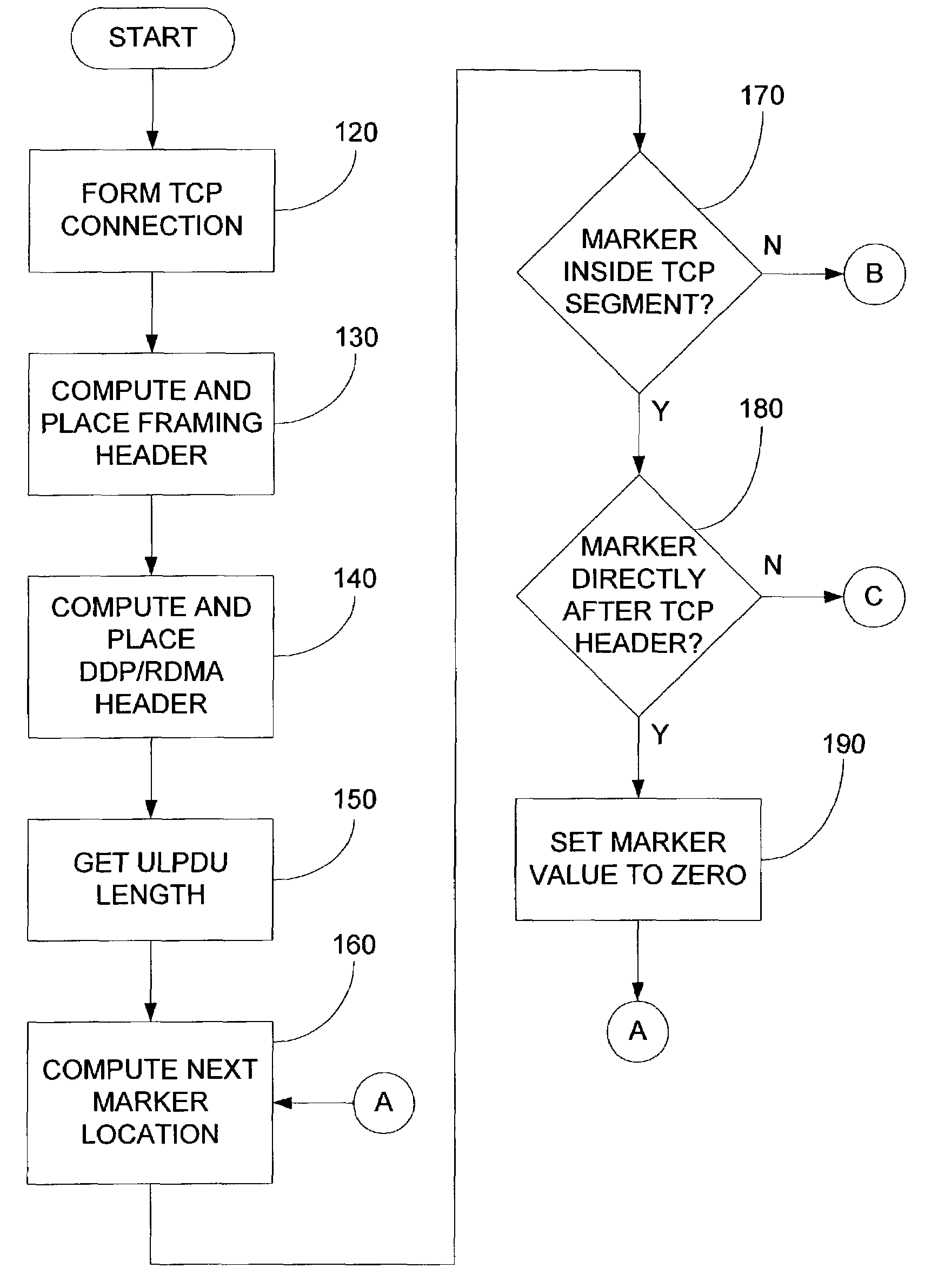
[0036]FIG. 3 shows an embodiment of a system that may provide a method for identifying Upper Layer Protocol (ULP) message boundaries. For example, the method may identify ULP message boundaries in a byte stream transport protocol (e.g., a framing protocol). A transmitter 10 (e.g., a client) may be coupled to a receiver 30 (e.g., a server) via a network 20 such as, for example, the internet. The network 20 may optionally include an intermediate box 40. A TCP connection may be initiated between the transmitter 10 and the receiver 30. The intermediate box 40 (e.g., a firewall) may terminate the TCP connection of the transmitter 10 and may initiate another TCP connection with the receiver 30. The intermediate box 40 may receive a first set of TCP frames from the transmitter 10 and resegment the first set of TCP frames into a second set of TCP frames. The resegmentation of the first set of TCP frames may, for example, result in smaller TCP frames. In such a case, the TCP frame scheme sen...


PUM


Abstract

Systems and methods that identify the Upper Layer Protocol (ULP) message boundaries are provided. In one example, a method that identifies ULP message boundaries is provided. The method may include one or more of the following steps: attaching a framing header of a frame to a data payload to form a packet, the framing header being placed immediately after the byte stream transport protocol header, the framing header comprising a length field comprising a length of a framing protocol data unit (PDU); and inserting a marker in the packet, the marker pointing backwards to the framing header and being inserted at a preset interval.

Description

RELATED APPLICATIONS[0001]This application makes reference to, claims priority to and claims benefit from U.S. Provisional Patent Application Ser. No. 60 / 363,381, entitled “Method of Identifying ULP Header in TCP Stream,” filed on Mar. 8, 2002; U.S. Provisional Patent Application Ser. No. 60 / 363,356, entitled “Method of Identifying ULP Header in TCP Stream,” filed on Mar. 11, 2002; U.S. Provisional Patent Application Ser. No. 60 / 372,852, entitled “Method for Marker Based Re-Segmentation Detection,” filed on Apr. 16, 2002; and U.S. Provisional Patent Application Ser. No. 60 / 372,851, entitled “Method for Marker Based Re-Segmentation Detection,” filed on Apr. 16, 2002.INCORPORATION BY REFERENCE[0002]The above-referenced United States patent applications are hereby incorporated herein by reference in their entirety.BACKGROUND OF THE INVENTION[0003]The transmission control protocol / internet protocol (TCP / IP) is a protocol that has become widely used for communications. However, receiving...

Claims


Application Information

Patent Timeline
Patent Type & Authority Patents(United States)
IPC IPC(8): H04L12/56H04L29/06
CPCH04L29/06217H04L69/16H04L69/161H04L69/22H04L69/166H04L65/1016
Inventor ELZUR, URI
Owner AVAGO TECH INT SALES PTE LTD
Why Eureka
Try Eureka