Method and system for far-field microscopy to exceeding diffraction-limit resolution

a technology of resolution and far-field microscopy, applied in the field of microscopy, can solve the problem that the spectral width of the second laser pulse is too wide to distinguish the fluorescence emission from the acceptor, and achieve the effect of avoiding obscuring the purpos

Inactive Publication Date: 2007-11-20
LASER MICROTECH
View PDF0 Cites 27 Cited by
  • Summary
  • Abstract
  • Description
  • Claims
  • Application Information

AI Technical Summary

Problems solved by technology

But, if the duration of the second laser pulse is too short, the spectrum width of the second laser pulse will be too wide to be distinguishable from the fluorescence emission from acceptors.

Method used


Image

  • Method and system for far-field microscopy to exceeding diffraction-limit resolution
  • Method and system for far-field microscopy to exceeding diffraction-limit resolution
  • Method and system for far-field microscopy to exceeding diffraction-limit resolution

Examples


Embodiment Construction

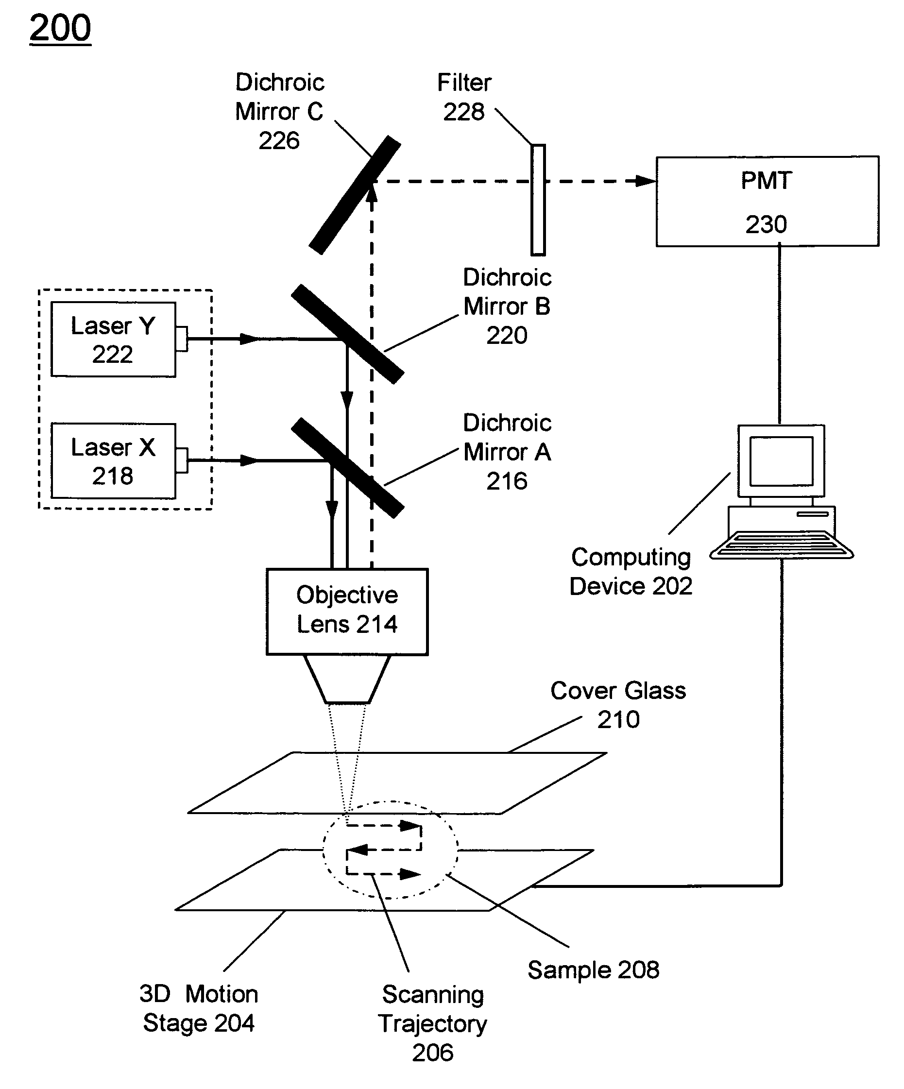
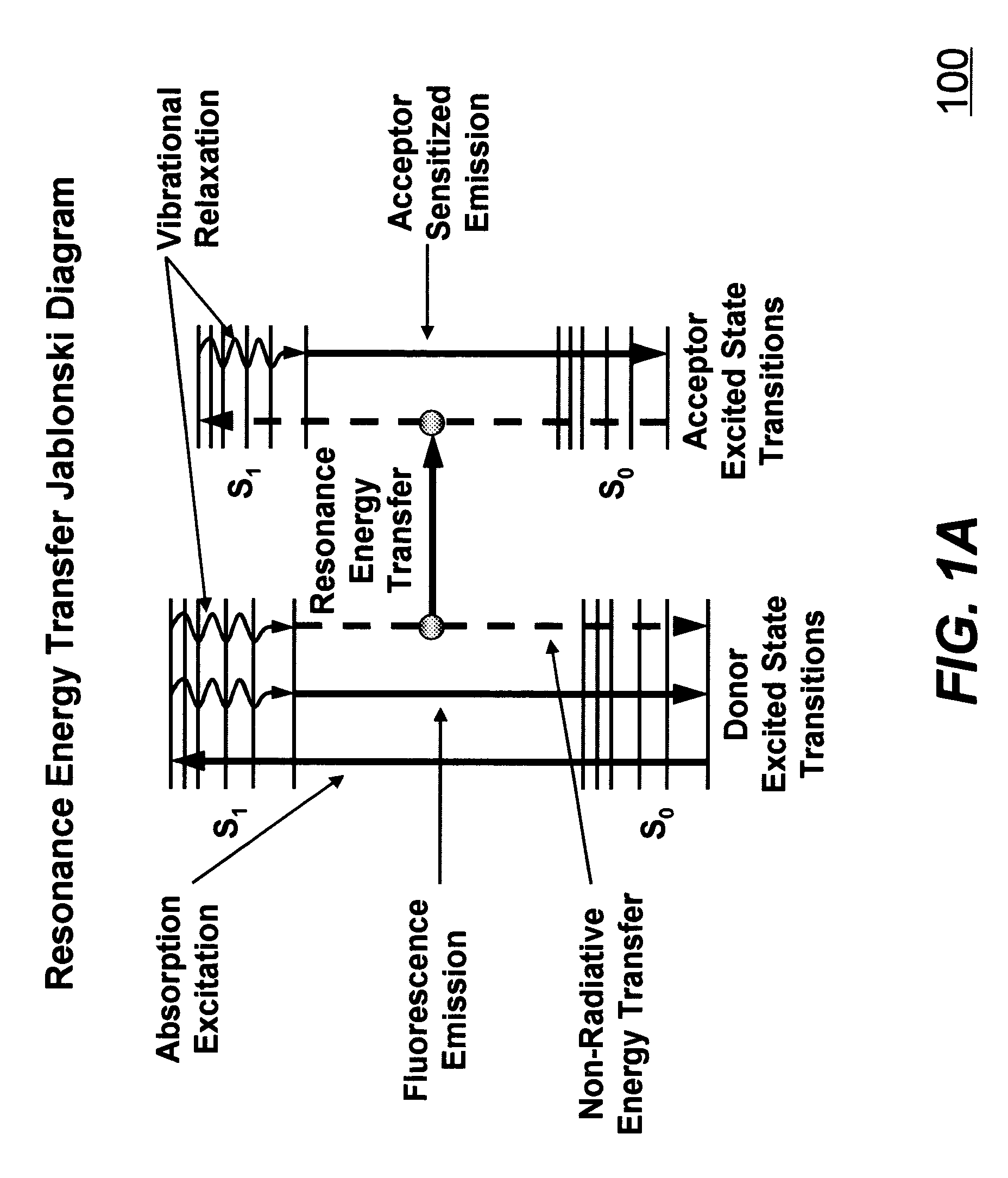
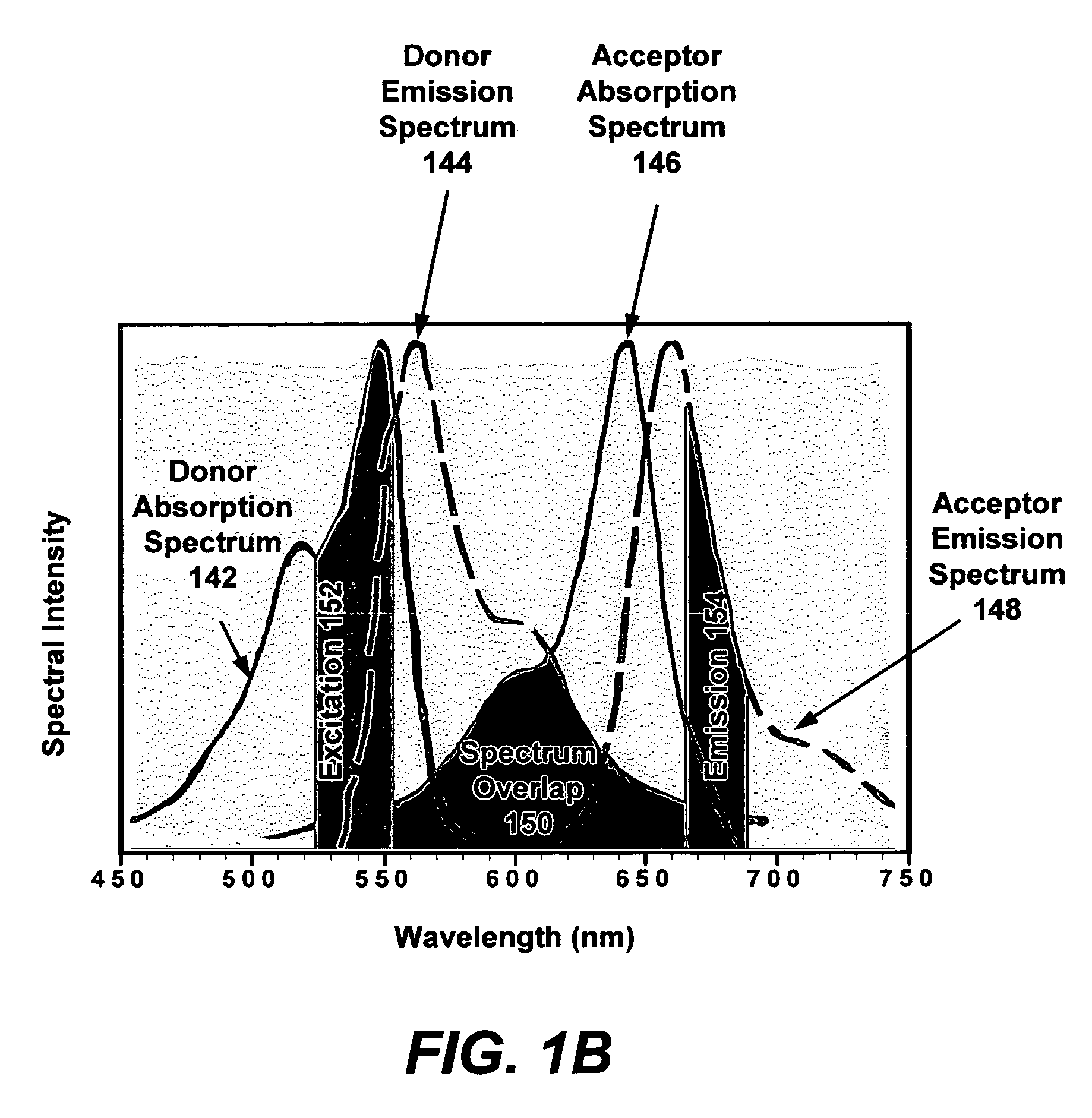
[0022]The present invention discloses the method and system as it pertains to exceeding diffraction-limit resolution in laser scanning fluorescence microscopy using fluorescence-resonance-energy-transfer-induced-emission-depletion (FRET-IED) technique. According to one aspect, the present invention applies two laser pulses to induce FRET-IED between controlled concentrations of donors and acceptors co-doped on a nanoparticle. As a result of this technique, the fluorescence emission from the acceptors is within a circular area smaller than that of the diffraction-limited focal spot.

[0023]In the following description, numerous specific details are set forth in order to provide a thorough understanding of the present invention. However, it will become obvious to those skilled in the art that the present invention may be practiced without these specific details. The descriptions and representations herein are the common means used by those experienced or skilled in the art to most effec...


PUM

PropertyMeasurementUnit
diameteraaaaaaaaaa
diameteraaaaaaaaaa
diameteraaaaaaaaaa

Abstract

The bio-sample (e.g., a live cell) is labeled with a proper number of nanoparticles. Each nanoparticle is pre-co-doped with a controlled ratio of fluorophore donors and acceptors. Two laser pulses are applied to the bio-sample. The first laser pulse has a center wavelength near the peak of absorption spectrum of acceptors. The intensity of first laser pulse is adjusted such that FRET saturation occurs near the center of the focal spot. The focal spot of the first laser pulse is a diffraction-limited Airy disk that has the highest laser intensity in the center of the focal spot. The second laser has a center wavelength in the emission spectrum of acceptors and with a uniform intensity distribution throughout the focal spot. The fluorescence emission from acceptors after two laser pulses is from an area that is smaller than the diffraction-limited focal spot. Hence, a higher than diffraction-limit resolution is achieved.

Description

BACKGROUND OF THE INVENTION[0001]1. Field of the Invention[0002]The present invention generally relates to the field of microscopy and more particularly to techniques for exceeding diffraction-limit resolution in far-field microscopy by using nanoparticles co-doped with donor-acceptor dyes, laser pulses, and the method of fluorescence-resonance-energy-transfer-induced-emission-depletion (FRET-IED).[0003]2. Description of the Related Art[0004]The advancement in biological research has progressed very rapidly in the last couple of decades. One of the important tools helping this progress is microscopy that is used to obtain an enlarged view of an object so that it is possible to observe details that otherwise could not be observed. In order to view the precise location and the nature of the interactions between, for example, specific molecular species in live cells, a conventional far-field optical laser scanning microscope (LSM) has been used. LSM is used to observe tiny objects unti...

Claims


Application Information

Patent Timeline
Patent Type & Authority Patents(United States)
IPC IPC(8): G01N21/64
CPCG01N21/6458B82Y15/00
Inventor TSAI, HAI-LUNGCHENG, YA
Owner LASER MICROTECH
Why Eureka
Try Eureka