Plasma treatment apparatus and plasma generation method

a plasma processing apparatus and plasma technology, applied in the field of plasma processing apparatus and plasma generation method, can solve the problems of unstable operation of the plasma processing apparatus after discharge and the tendency to occur of abnormal discharg

Inactive Publication Date: 2007-12-11
TOKYO ELECTRON LTD
View PDF11 Cites 8 Cited by
  • Summary
  • Abstract
  • Description
  • Claims
  • Application Information

AI Technical Summary

Benefits of technology

[0012]The present invention has been made to solve these problems, and has its object to stabilize the operation of a plasma processing apparatus which performs circular polarization feeding.

Problems solved by technology

Then, abnormal discharge tends to occur, and the operation of the plasma processing apparatus after discharge does not stabilize.
Accordingly, these problem similarly occur in not only the high-frequency plasma processing apparatus described above but also an ECR plasma processing apparatus which feeds circular polarization into a processing vessel.

Method used


Image

  • Plasma treatment apparatus and plasma generation method
  • Plasma treatment apparatus and plasma generation method
  • Plasma treatment apparatus and plasma generation method

Examples


first embodiment

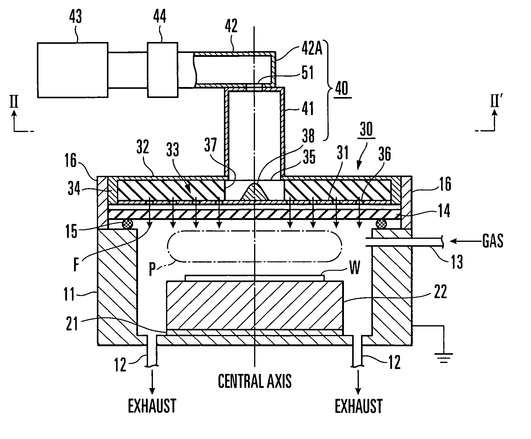
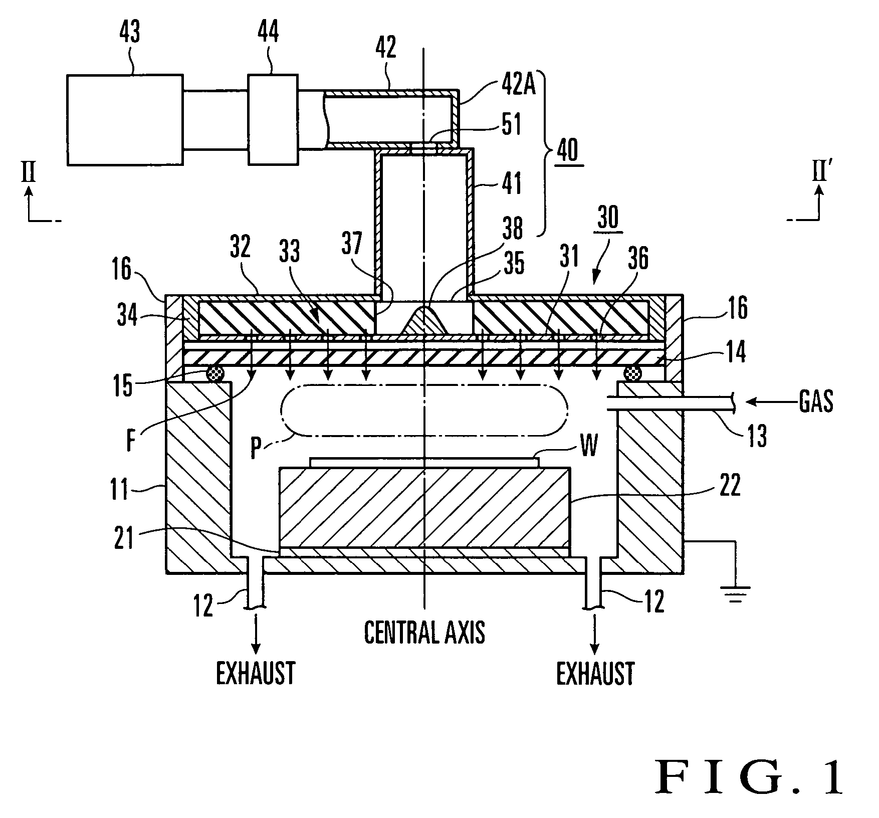
[0042]FIG. 1 shows the arrangement of a high-frequency plasma processing apparatus according to the first embodiment of the present invention. This plasma processing apparatus has a processing vessel 11 which accommodates a substrate (target object) W such as a semiconductor or LCD and processes the substrate W with a plasma, an RLSA 30 which supplies a high-frequency electromagnetic field F into the processing vessel 11 and generates a plasma P in the processing vessel 11 by the operation of the high-frequency electromagnetic field F, and a power feed unit 40 which supplies the high-frequency electromagnetic field to the RLSA 30 by circular polarization feeding.

[0043]The processing vessel 11 is a bottomed cylinder with an upper opening. A table 22 is fixed to the central portion of the bottom surface of the processing vessel 11 through an insulating plate 21. The substrate W is placed on the upper surface of the table 22.

[0044]Exhaust ports 12 for vacuum evacuation are formed in th...

second embodiment

[0065]FIG. 3 is a view showing the arrangement of part of a high-frequency plasma processing apparatus according to the second embodiment of the present invention. FIG. 3 shows the arrangement of a power feed unit. The same or equivalent portions as in FIG. 1 are denoted by the same reference numerals, and a description thereof will be omitted when appropriate.

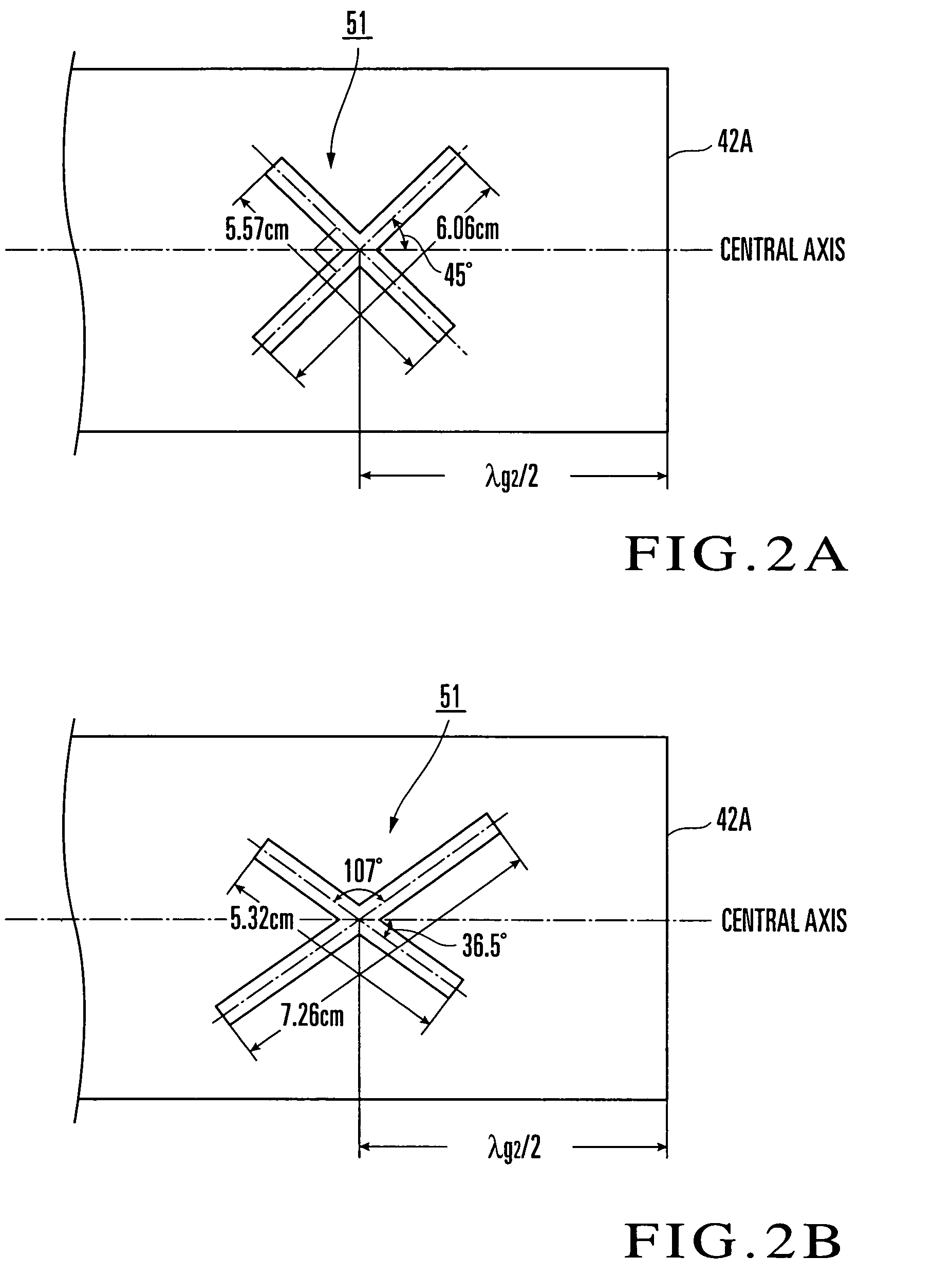
[0066]In the power feed unit 40 shown in FIG. 1, the cross slot 51 is formed in the E-surface of the rectangular waveguide 42. In a power feed unit 40A shown in FIG. 3, a cross slot 53 is formed in the terminal end face of a rectangular waveguide 45. The first and second embodiments are different from each other in this respect. The second embodiment will be described mainly on this difference with reference to FIGS. 3 and 4.

[0067]FIG. 4 is a plan view showing an arrangement of the cross slot 53 formed in the terminal end face of the rectangular waveguide 45 when the terminal end face of the rectangular waveguide 45 is seen fr...

third embodiment

[0072]FIG. 7 is a view showing the arrangement of part of a high-frequency plasma processing apparatus according to the third embodiment of the present invention. FIG. 7 shows the arrangement of a power feed unit. The same or identical portions as in FIG. 1 are denoted by the same reference numerals, and a description thereof will be omitted when appropriate.

[0073]The power feed unit shown in FIG. 7 supplies a high-frequency electromagnetic field into a cylindrical waveguide 41 as a rotating electromagnetic field by using a patch antenna 71 which operates as a circular polarization antenna. The patch antenna 71 includes a grounded circular conductor plate (first conductor plate) 41A which closes one end of the cylindrical waveguide 41, a dielectric plate 72 arranged on the lower surface of the circular conductor plate 41A, and a conductor plate (second conductor plate) 73 which opposes the circular conductor plate 41A through the dielectric plate 72. In the following description, in...


PUM

PropertyMeasurementUnit
relative dielectric constantaaaaaaaaaa
frequencyaaaaaaaaaa

Abstract

A plasma processing apparatus includes a table (22) on which a processing target (W) is to be placed, a processing vessel (11) where the table is to be accommodated, and a power feed unit (40) for supplying a high-frequency electromagnetic field (F) into the processing vessel. The power supply unit includes at least a cylindrical waveguide (41) for introducing the high-frequency electromagnetic field, and a circular polarization antenna (51) arranged at one end of the cylindrical waveguide to supply the high-frequency electromagnetic field as a rotating electromagnetic field rotating in a plane perpendicular to its traveling direction. Accordingly, there is no need of providing a circular polarization converter for converting the high-frequency electromagnetic field in the cylindrical waveguide into the rotating electromagnetic field. Consequently, it is possible to solve problems caused by the circular polarization converter, stabilize the operation of plasma generation by performing circular polarization feeding, and perform a continuous operation for a long period of time.

Description

BACKGROUND OF THE INVENTION[0001]The present invention relates to a plasma processing apparatus and plasma generation method.[0002]More specifically, the present invention relates to a plasma processing apparatus and plasma generation method which generate a plasma by an electromagnetic field supplied into a processing vessel using a slot antenna.[0003]The present invention also relates to a plasma processing apparatus and plasma generation method which generate a plasma by using electrons heated by electron-cyclotron-resonance (ECR).[0004]In the manufacture of a semiconductor device or flat panel display, plasma processing apparatuses are used often to perform processes such as formation of an oxide film, crystal growth of a semiconductor layer, etching, and ashing. Among the plasma processing apparatuses, a high-frequency plasma processing apparatus is available which supplies a high-frequency electromagnetic field into a processing vessel by using a slot antenna and ionizes and d...

Claims


Application Information

Patent Timeline
Patent Type & Authority Patents(United States)
IPC IPC(8): C23C16/00C23F1/00H01L21/306B01J19/08C23C16/511H05H1/46H01J37/32H01L21/205H01L21/302H01L21/3065
CPCH01J37/32293H01J37/32192H01P1/173
Inventor ISHII, NOBUO
Owner TOKYO ELECTRON LTD
Why Eureka
Try Eureka