

Cutting insert having a rake surface and a plateau surface separated by a step
a technology of cutting inserts and plateaus, which is applied in the field of cutting inserts, can solve the problems that deposits cannot adversely affect the correct indexing of cutting inserts, and achieve the effects of reducing the tendency of material accumulation, good protection, and great heigh
- Summary
- Abstract
- Description
- Claims
- Application Information
AI Technical Summary
Benefits of technology
Problems solved by technology
Method used
Image

Examples
Embodiment Construction
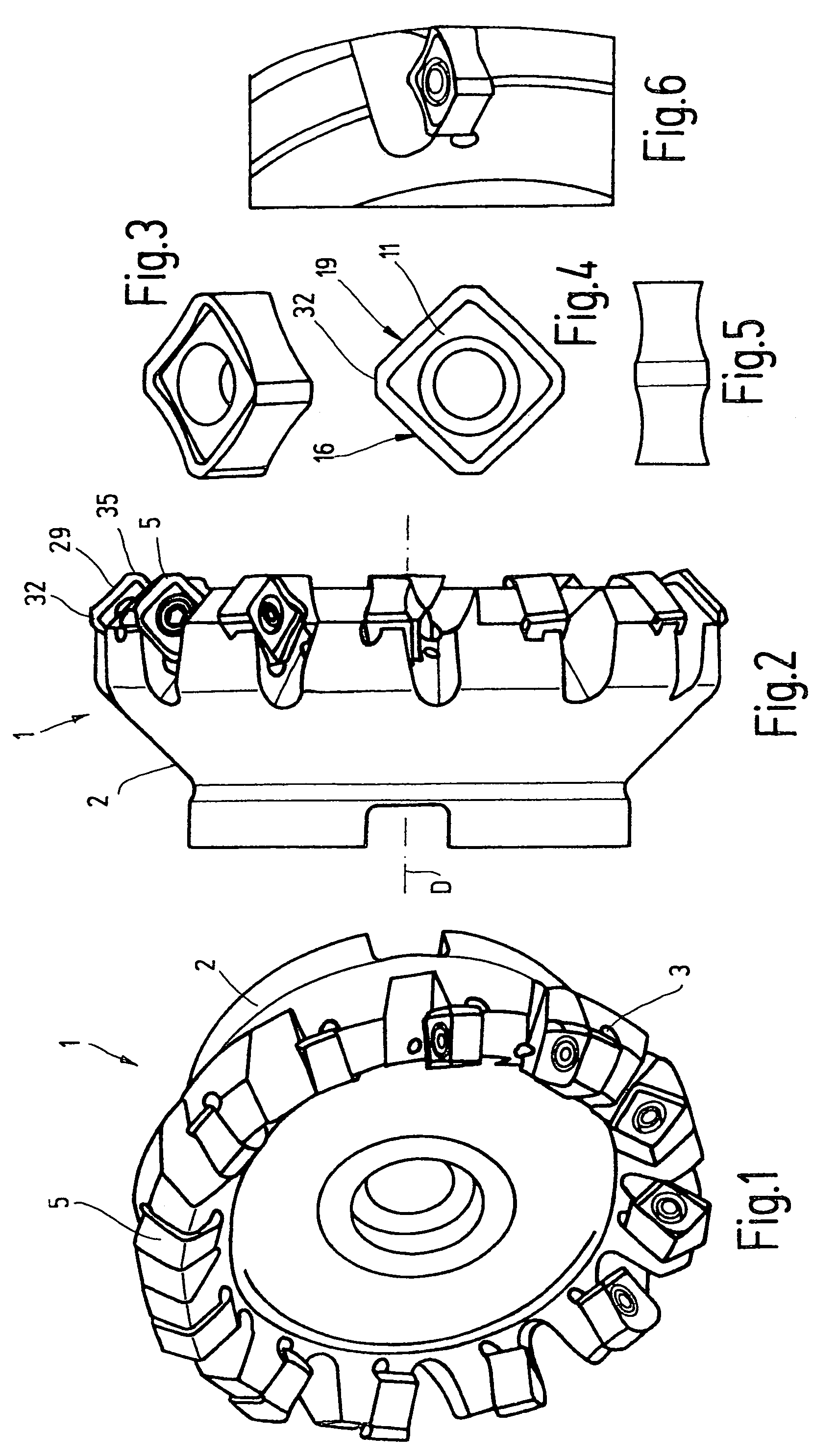
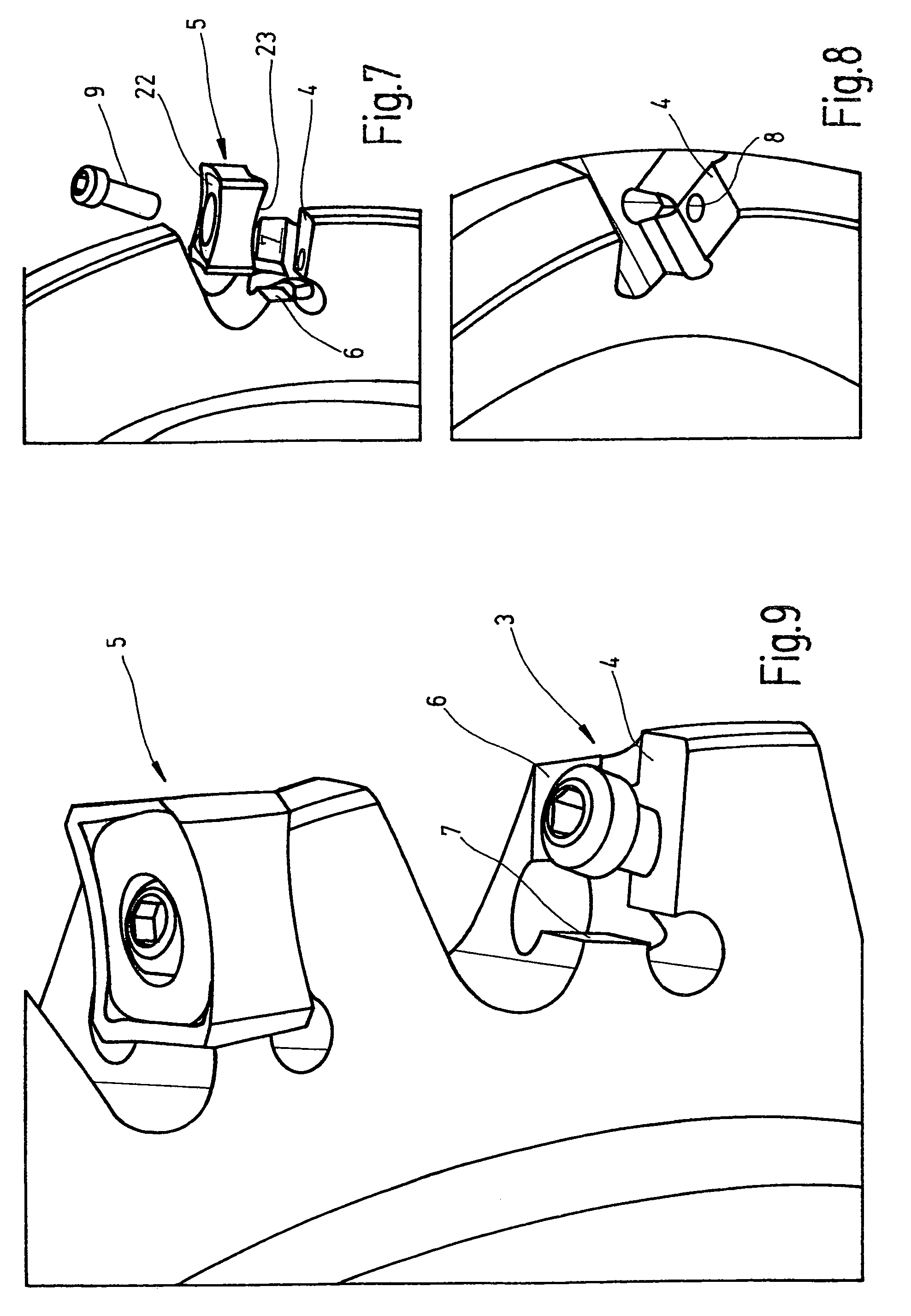
[0045]FIG. 1 shows a face-milling cutter 1, including a tool body 2 provided with insert seats 3. The insert seat 3, which is shown separately in FIG. 9, has a planar seating surface 4 for directly contacting a cutting insert 5. The seating surface 4 is, for example, rectangular, and is free-standing along all four edges (see especially FIG. 8). Adjacent the seating surface 4 at least two lateral supporting surfaces 6, 7 are provided, which are oriented perpendicularly to the seating surface 4 and are spaced respectively from two of the seat's edges.
[0046]The lateral supporting surfaces 6, 7 are formed directly on the tool body 2 and belong to the insert seat 3 for lending a lateral support to the cutting insert. Also referring to FIGS. 7 and 8, at the insert seat a threaded bore 8 is formed which passes through the seating surface 4 at a slight oblique angle thereto and with which a securing screw 9 is associated. On the tool body 2 additional cutting insert seats are arranged whic...
PUM
| Property | Measurement | Unit |
|---|---|---|
| Angle | aaaaa | aaaaa |
| Angle | aaaaa | aaaaa |
| Shape | aaaaa | aaaaa |
Abstract
Description
Claims
Application Information