Steerable dilatation system, dilator, and related methods for stepped dilatation

a dilatation system and dilatation system technology, applied in the field of medical dilatation, can solve the problems of difficult economic choice, perforation of the cavity or organ wall, and ever-present risk, and achieve the effects of increasing lubricity, enhancing step dilatation according to either method, and ensuring the controller's involvemen

Inactive Publication Date: 2007-12-11
OPTIVIA MEDICAL
View PDF28 Cites 8 Cited by
  • Summary
  • Abstract
  • Description
  • Claims
  • Application Information

AI Technical Summary

Benefits of technology

[0013]As already noted, a distinct advantage of the present invention is that the dilator, though providing visualization and fluid distension, insufflation, and irrigation capabilities can be made economically so that it need not be sterilized but rather is simply disposed of after a single use. The dilator, however, is adapted to detachably connect to a reusable or disposable handle. The handle according to the present invention easily connects to the dilator and, more specifically, engages the controller associated with the dilatation shaft and distal tip. Preferably, the handle includes a dilatation channel formed in the handle so that the dilatation shaft can be readily received and retained therein. The handle preferably also includes a manifold channel formed in the handle to receive and retain therein the manifold of the dilator. The handle further preferably includes at least one supply tube channel also formed in the handle to receive and retain therein the at least one supply tube connected to the manifold of the dilator.
[0014]A particular advantage provided by the handle is a control actuator positioned thereon and adapted to readily engage the controller associated with the dilator when the dilator is detachably connected with the handle. Specifically, the control actuator preferably is positioned to be responsive to finger or thumb deflection supplied by a user holding the handle and controllably steering the dilator using a single hand.
[0015]The system and, in particular, the dilator of the present invention advantageously enable distinct methods of dilating a bodily opening in a step-dilatation manner. According to one such method, a distal region of a dilatation shaft is inserted into an opening in the body while on a proximal region of the shaft is slidably positioned at least one spacer and a cannula. The at least one spacer then is slidably moved over at least a portion of the distal region of the shaft while the cannula remains positioned at the proximal region of the shaft. The radial diameter of the at least one spacer is greater than that of the dilatation shaft so that advancing the spacer into the opening over the distal region of the shaft dilates the opening. The cannula is then slidably moved over at least a portion of the spacer while the spacer remains in position over the distal region of the shaft.
[0016]Alternatively, step dilatation can be achieved using a cannula having at least a medial portion adapted to radially expand. According to this method, the cannula is slidably positioned on the shaft of the dilator and the dilator and cannula inserted into a body opening. A spacer is selected to have a larger radial diameter than that of the cannula and the dilator shaft is withdrawn leaving the cannula within the body opening. The spacer is slidably positioned over the shaft and inserted into the cannula positioned within the bodily opening to thereby radially expand the cannula.
[0017]Step dilatation according to either method can be enhanced by visualizing an actual or potential space within the body using a fiber optic scope (or camera-tipped scope or other imaging-tipped scope) positioned within the lumen formed in the dilatation shaft. Each method further can be enhanced by irrigating and / or distending tissue within the body with a fluid, e.g., gas or liquid, delivered via the lumen of the shaft. Specifically, the fluid delivered into the body aids step dilatation in a number of distinct ways. The fluid, for example, can provide increased lubricity in and around the dilator, easing the advancement of the dilatation shaft. The fluid, moreover, also creates fluid pressure against the cavity walls and tissue. Thus, as the dilator is advanced into the body and as step dilatation proceeds within a bodily opening the pressure of the fluid introduced into the body increases, thereby adding to the forces tending to distend tissue and further dilate the bodily opening. Accordingly, the fluid delivery can irrigate a passage for the dilator and also can provide fluid pressure that cooperates with the forces provided by the spacer and the cannula in dilating the bodily opening.
[0018]The present invention also provides a disposable dilator kit usable by a physician, veterinarian, or other qualified medical personnel to dilate a portion of a human or an animal body opening with a visually guided, fluid facilitated steerable dilator. The kit provides a distinct benefit, for example, in that it provides a single convenient source of elements necessary for inducing dilatation in a patient. The kit can conveniently be positioned within ready reach of an attending physician or other qualified medical personnel. Moreover, the kit can be conveniently transported by a physician, physician's assistant, or nurse to a site where dilatation is to be induced in a patient.

Problems solved by technology

A serious drawback of these conventional devices recognized by Applicants is that they necessitate the physician's estimating how far into the body the device extends and where within the body the device is positioned.
This limitation forces a physician using such a device to slowly probe with the tip of the device inside a patient's body as the device is inserted into the body.
This poses the ever-present risk that if the physician misjudges the position of the dilatation device, the wall of cavity or organ may be perforated.
Another drawback of these conventional devices recognized by Applicants is that they pose a difficult economic choice in the sense that each dilatation device must be either disposed of after only one use—in which case, each such device will need to be relatively inexpensive to manufacture—or otherwise it must be sterilized.
Viruses and bacteria can be trapped on the surfaces of such devices.
Moreover, the lubricants applied during the use of such devices, if they remain on the device's surface, can trap microbes on the surface.
These methods, however, can be expensive and can reduce the operative life of the instrument.
Moreover, there is a growing recognition by others that repeated use of antibiotics for sterilization (and other) purposes can reduce their effectiveness.

Method used


Image

  • Steerable dilatation system, dilator, and related methods for stepped dilatation
  • Steerable dilatation system, dilator, and related methods for stepped dilatation
  • Steerable dilatation system, dilator, and related methods for stepped dilatation

Examples


Embodiment Construction

[0050]The present invention will now be described more fully hereinafter with reference to the accompanying drawings which illustrate preferred embodiments of the invention. This invention may, however, be embodied in many different forms and should not be construed as limited to the illustrated embodiments set forth herein. Rather, these embodiments are provided so that this disclosure will be thorough and complete, and will fully convey the scope of the invention to those skilled in the art. Like numbers refer to like elements throughout. The prime notation, if used, indicates similar elements in alternative embodiments.

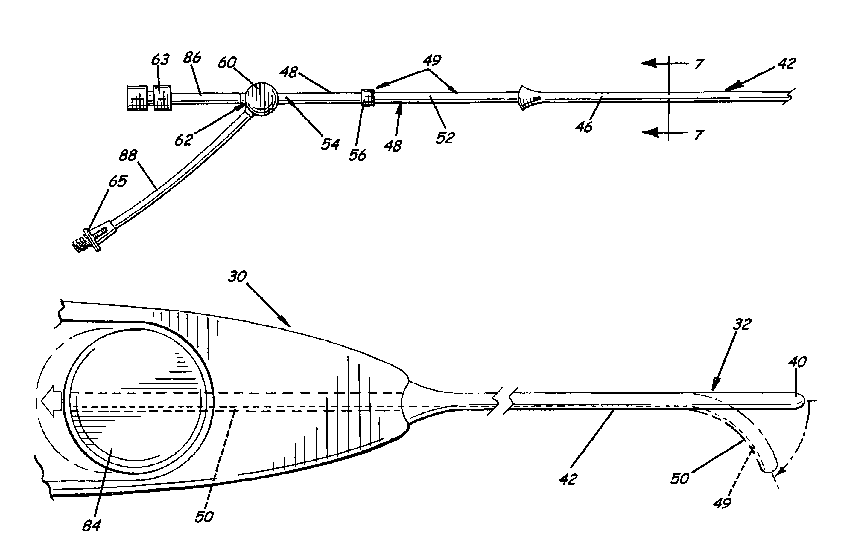
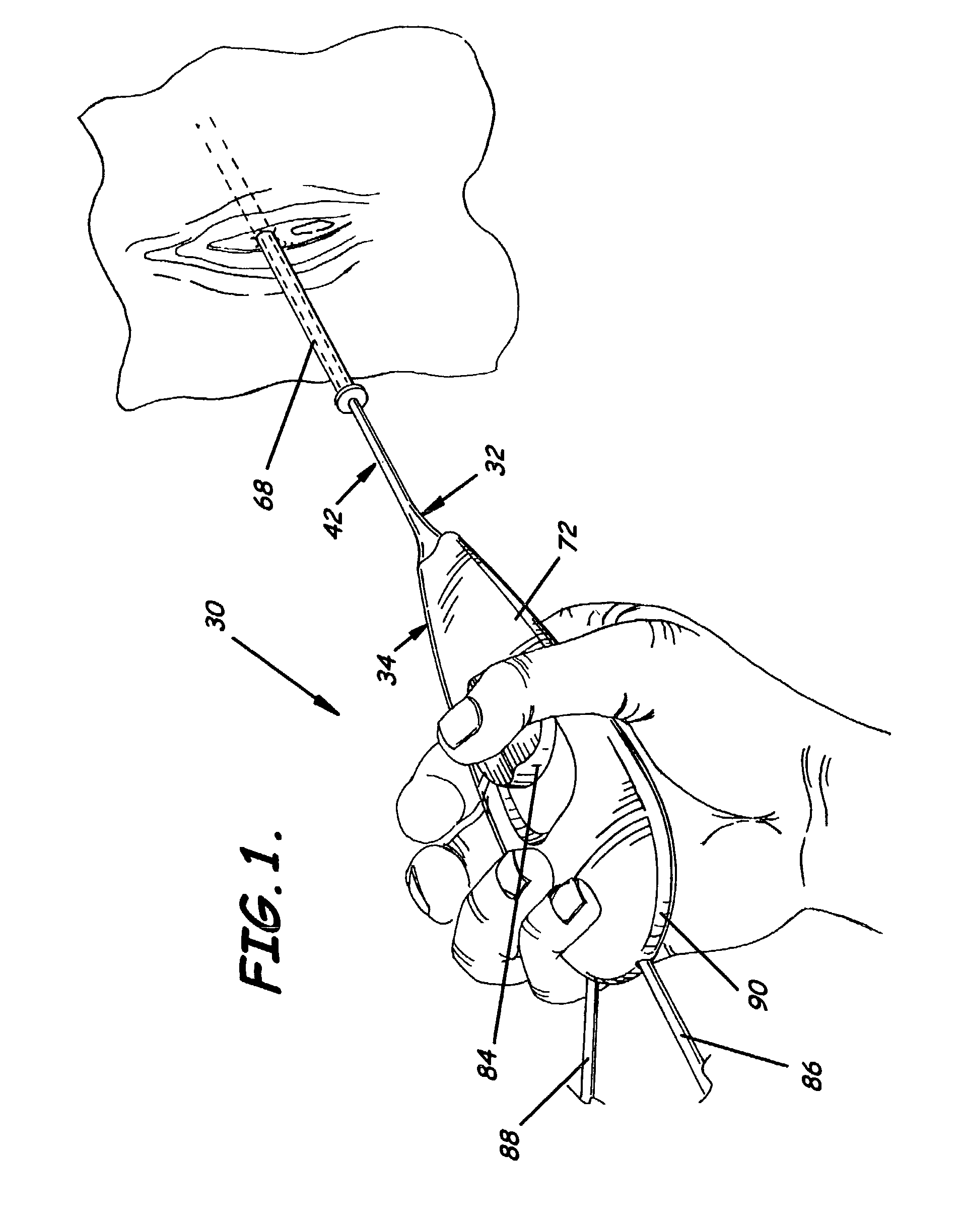
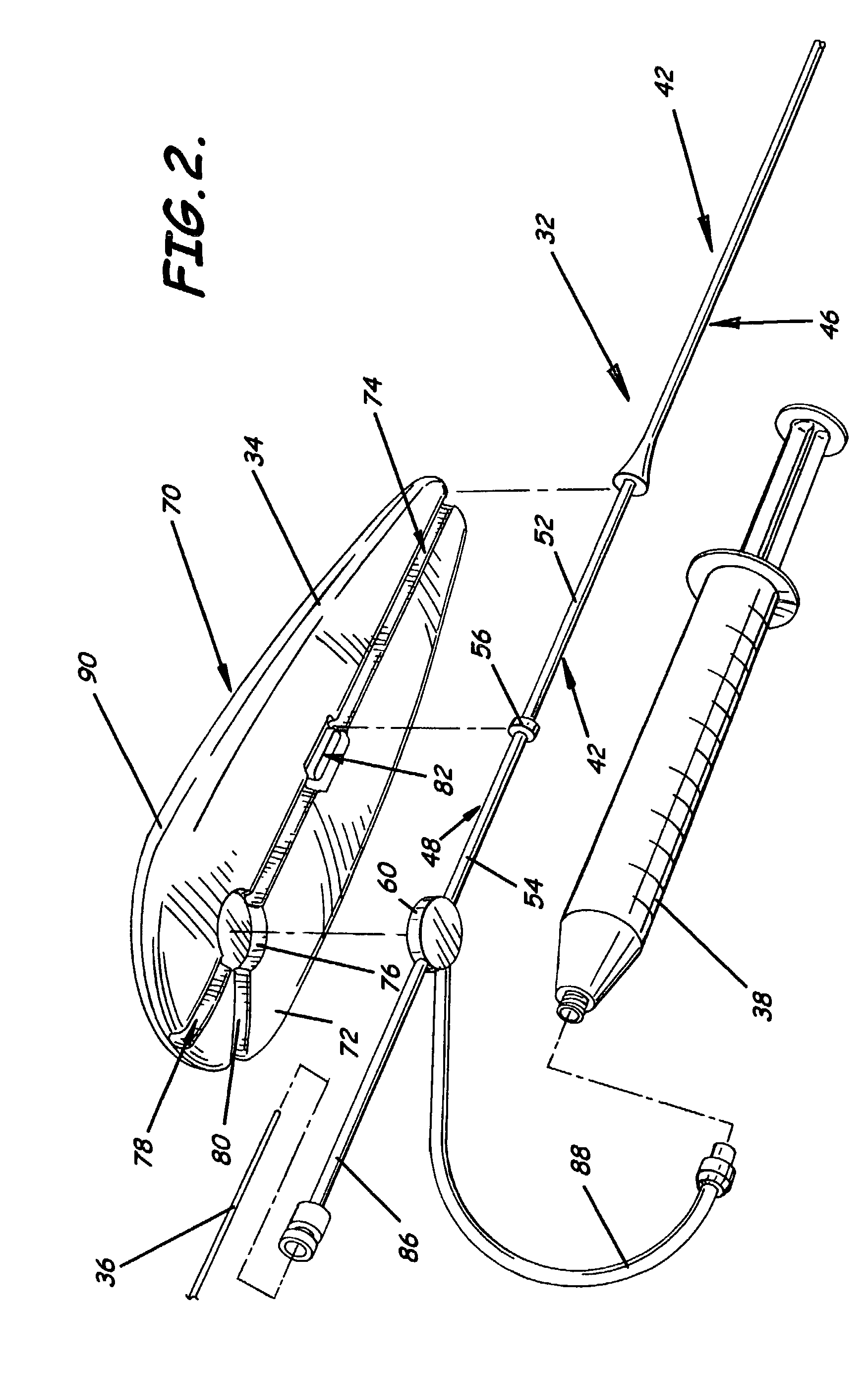
[0051]FIGS. 1, 2, and 6-13 illustrate a visually guided steerable stepwise dilatation system 30 for use in dilating a cavity, canal, blood vessel, or actual or potential space within a human or animal body. The system preferably has a dilator 32, a handle 34, a fiber optic scope 36, camera on a scope 36′, or other imaging device, and a fluid supply 38. The dilator ...


PUM


Abstract

A dilatation system preferably including a dilator and a detachable handle for achieving step dilatation of a bodily opening is provided. The dilator preferably is steerable and can be visually guided using a fiber optic scope positioned in a lumen formed in a shaft of the dilator. Fluid can be delivered through the lumen with the scope positioned therein so as to distend, irrigate, or insufflate a space within the body. A kit and related methods also are provided that can include elements desired to facilitate step dilatation of a body opening.

Description

RELATED APPLICATIONS[0001]This is a non-provisional patent application which claims the priority of provisional patent application U.S. Ser. No. 60 / 349,390, filed Jan. 17, 2002, and titled Steerable Dilatation System, Dilator, and Related Methods for Stepped Dilatation, which is incorporated herein by reference in its entirety.FIELD OF THE INVENTION[0002]The present invention relates generally to medical dilators and, more specifically, to a steerable dilator for dilating a cavity, canal, blood vessel, or other opening in a human or animal body.BACKGROUND OF THE INVENTION[0003]Physicians and veterinarians frequently rely on methods of dilatation of a natural opening in a body (e.g., the urethra) to gain greater access to internal areas of the body without making an incision and cut through tissue of the body. A not infrequent purpose of this procedure of dilating a cavity, canal, duct, blood vessel or other bodily opening is to enlarge the opening so as to permit the insertion of in...

Claims


Application Information

Patent Timeline
Patent Type & Authority Patents(United States)
IPC IPC(8): A61M37/00A61B1/12A61B1/32A61B17/00A61M25/01A61M29/00
CPCA61B1/12A61B1/32A61M29/00A61M25/0136A61B2017/003A61M25/0147A61B2017/0046
Inventor MASSEY, JOE B.SNOKE, PHILLIP JACK
Owner OPTIVIA MEDICAL
Why Eureka
Try Eureka