
Biochip type device

a biochip and chip technology, applied in the direction of fluorescence/phosphorescence, instruments, material analysis, etc., can solve the problems of poor energy efficiency and cost, difficult to locate with sufficient accuracy, poor energy efficiency, etc., and achieve the effect of increasing measurement sensitivity

Inactive Publication Date: 2007-12-11
CENT NAT DE LA RECHERCHE SCI +2
View PDF8 Cites 5 Cited by
  • Summary
  • Abstract
  • Description
  • Claims
  • Application Information

AI Technical Summary

Benefits of technology

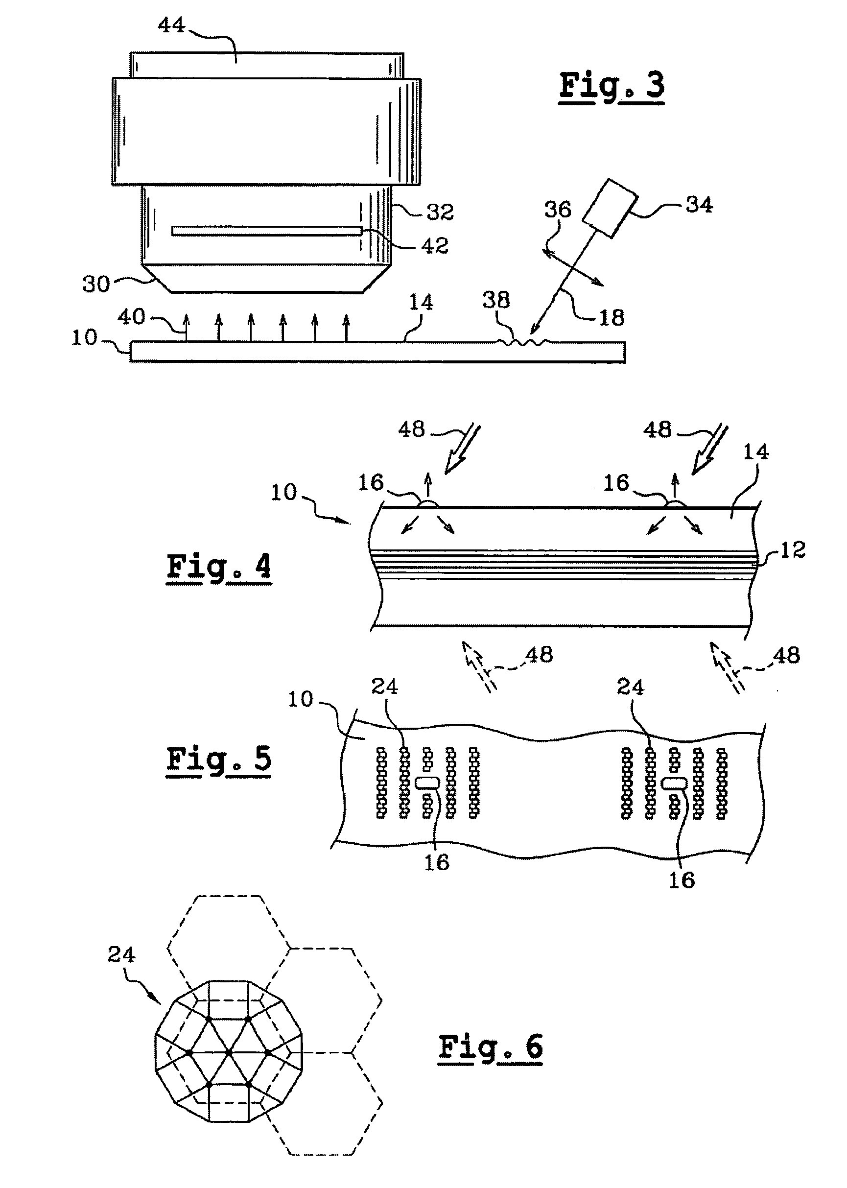
[0009]A particular object of the present invention is to increase measurement sensitivity by modifying the optical environment of each chromophore element, thus making it possible to pick up and concentrate on detection and measurement means a larger quantity of the light that is emitted by the chromophore elements.
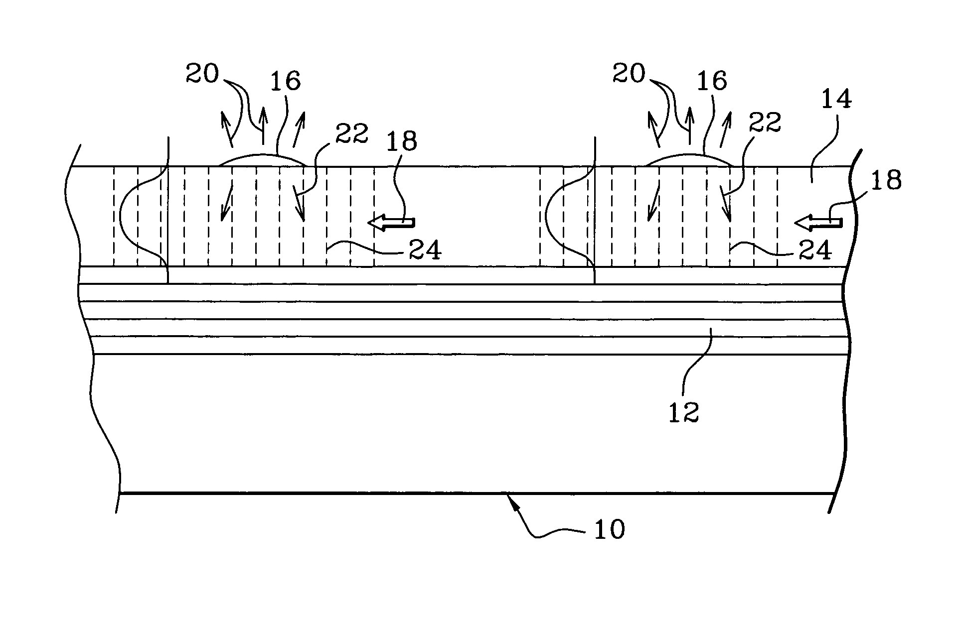
[0011]In the device of the invention, each chromophore element carried by the layer of high index material radiates most of its light emission into said material at angles that are below the critical angle, so that the radiation is converted into guided mode within the layer of high index material. The diffracting three-dimensional configuration or structuring of said layer in the vicinity of each chromophore element enables the radiation in guided mode to be extracted and directed towards the detection and measurement means.
[0015]This resonant microcavity placed under the chromophore elements is of a thickness that is selected to deliver a maximum amount of the light emitted by the chromophore elements towards the detection and measurement means. The effect due to this resonant microcavity combines with the effect due to extracting guided-mode light from the layer of high index material, thereby providing maximum effectiveness in picking up and concentrating the light emitted by each chromophore element.
[0021]In general, the device of the invention makes it possible to obtain a signal / noise ratio that is higher than in the prior art and to reject effectively the light for exciting the chromophore elements. This makes it possible to perform measurements in parallel by imaging the device, and also makes it possible to extend the operation of the device to a plurality of wavelengths.

Problems solved by technology

In addition, the trend is to place ever increasing numbers of probes on substrates of very small dimensions, so that it becomes very difficult to locate with sufficient accuracy, and thus identify, the probes that are carrying the chromophore elements from which the detected light signals originate.
The conventional solutions usually implemented for solving this problem consist in increasing the signal level exciting the chromophore elements in order to increase the response light therefrom, or else in increasing the quantity of molecules that couple and / or the quantity of probes, however those means are not very satisfactory for reasons of poor energy efficiency and cost.
Increasing the intensity of light excitation runs the risk of photodegradation of the molecules, and increasing the quantities of coupled molecules and probes requires an increase in the quantities of reagents used, which reagents are expensive.
Other known means use optical detection systems of very wide numerical aperture and / or immersed systems (in order to increase refractive index) but they are not very compatible with requirements for rapid scanning of arrays of probes on substrates.

Method used


Image

  • Biochip type device
  • Biochip type device
  • Biochip type device

Examples


Embodiment Construction

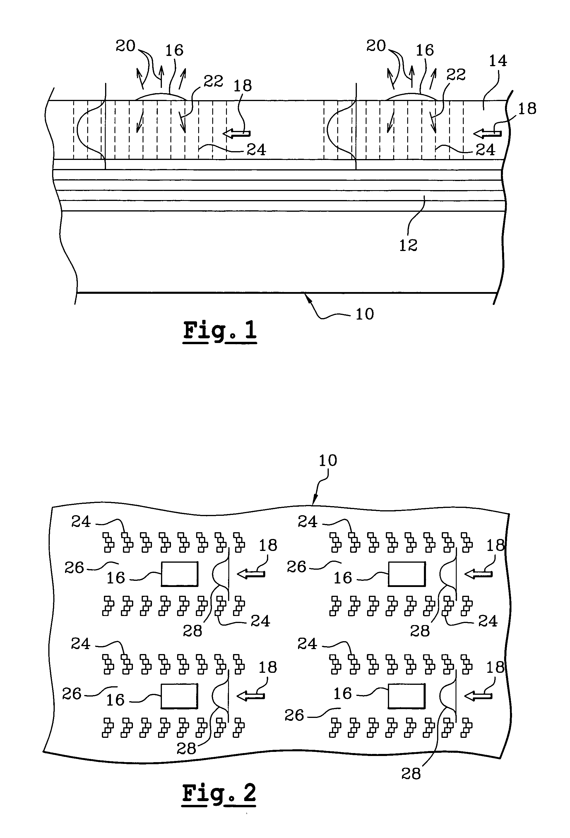
[0029]In the embodiment of FIGS. 1 and 2, reference 10 designates a substrate of any suitable material, e.g. glass, silica, metal, semiconductor material, or oxide, the substrate including an intermediate non-absorbent multilayer mirror 12 made up of a plurality of dielectric or metallic layers covered in a layer 14 of material having a relatively high refractive index, i.e. in this case a material whose refractive index is greater than or equal to 1.6. For example, the material may be TiO2 which has a refractive index equal to 2.4.

[0030]Chromophore elements 16 are fixed to the top face of the layer 14.

[0031]As mentioned above, these chromophore elements may be formed by probes fixed on the top face of the layer 14, or by molecules for analysis that become coupled with the probes that match them.

[0032]These probes constitute an array on the surface of the layer 14 and they are located in known positions.

[0033]Typically, the chromophore elements 16 are on squares of a side lying in t...


PUM


Abstract

An improved biochip type device comprising a substrate (10) including an intermediate non-absorbent multilayer mirror (12) covered by a layer (14) of high refractive index material having chromophore elements (16) fixed thereon, the layer (14) further including feature (24) for extracting guided-mode light in order to recover the light emitted by the chromophore elements (16) into the layer (14) in response to light excitation, and direct the light to detection and measurement means.

Description

[0001]This application is a Continuation of copending PCT International Application No. PCT / FR02 / 03975 filed on Nov. 20, 2002, which designated the United States, and on which priority is claimed under 35 U.S.C. § 120, and 35 U.S.C. § 119(a) on patent application Ser. No(s). 01 / 15140 filed in France on Nov. 22, 2001, the entire contents of which are hereby incorporated by reference.FIELD OF THE INVENTION[0002]The invention relates to an improved biochip type device comprising a substrate, chromophore elements carried by the substrate, and means for picking up and concentrating the light emitted by the chromophore elements.BACKGROUND OF THE INVENTION[0003]Known techniques for detecting and quantifying chemical or biological molecules, and in particular nucleic acids, oligonucleotides, proteins, polypeptide sequences, or fragments of such compounds, make use of biochip type devices comprising substrates that are generally made of glass, silica, metal, or nylon, and having fixed thereo...

Claims


Application Information

Patent Timeline
IPC IPC(8): G01N21/01G01N21/64G01N21/55G01N21/77
CPCG01N21/7703G01N21/648
Inventor WEISBUCH, CLAUDEBENISTY, HENRI
Owner CENT NAT DE LA RECHERCHE SCI
Learn More