
Insulation system with condensate wicking for vertical applications

a technology of condensate wicking and vertical installation, which is applied in the direction of defrosting, heating types, domestic cooling apparatus, etc., can solve the problems of water vapor migration and condensation, reducing the insulation efficiency, and excessive accumulation in the lower portion of vertical installation and/or adjoining horizontal portions of installation, so as to improve the insulation performance and reduce damage and deterioration

Inactive Publication Date: 2007-12-18
OWENS CORNING INTELLECTUAL CAPITAL LLC
View PDF10 Cites 12 Cited by
  • Summary
  • Abstract
  • Description
  • Claims
  • Application Information

AI Technical Summary

Benefits of technology

The solution improves insulation performance by reducing condensate accumulation and associated damage, maintaining efficiency and effectiveness in vertical installations by using capillary surface materials to manage condensate flow and evaporation.

Problems solved by technology

However, over time, and especially if, as is often the case, the facing is damaged, water vapor will migrate to and condense on the cool surface.
This condensate will accumulate and will enter the adjacent insulating material, thereby reducing its insulating efficiency.
These problems can be exacerbated in vertical installations due to the tendency of the condensate to flow downwardly along or adjacent the vertical surfaces resulting in excessive accumulation in the lower portions of the vertical installations and / or in adjoining horizontal portions of the installation.
Although this approach works well for substantially horizontal applications, the condensate accumulation associated with components or installations incorporating significant vertical surfaces tends to result in accumulations of condensate in the lower portion of the vertical installation that reduce the effectiveness of such solutions.

Method used


Image

  • Insulation system with condensate wicking for vertical applications
  • Insulation system with condensate wicking for vertical applications
  • Insulation system with condensate wicking for vertical applications

Examples


Embodiment Construction

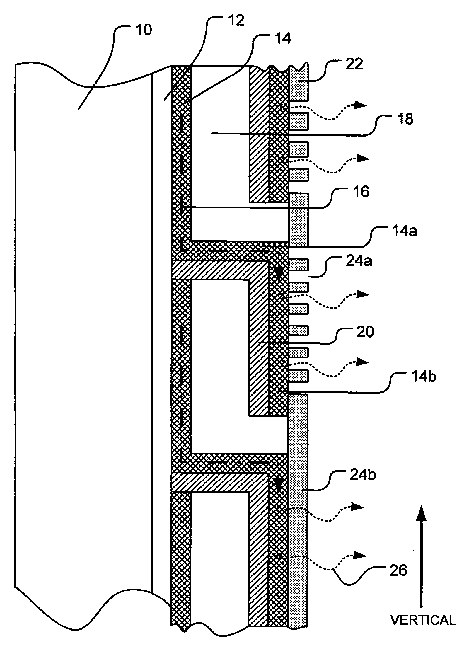
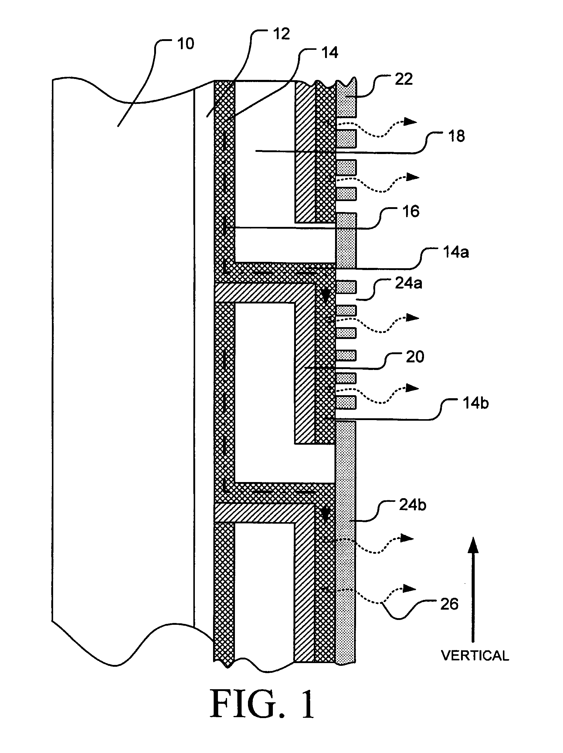
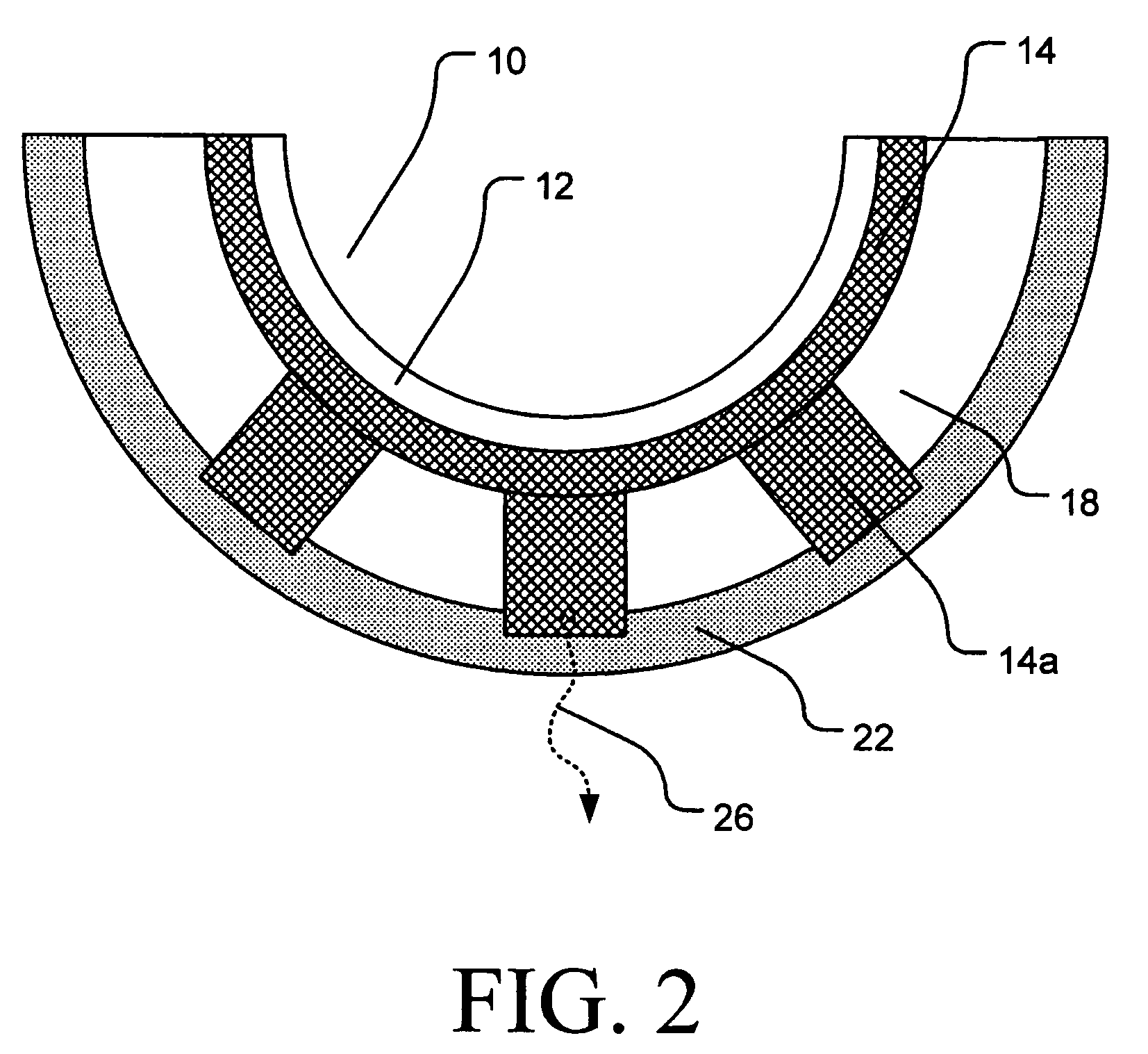
[0021]As shown in FIG. 1, an elongated, vertically-oriented duct, pipe or other structure 10 having a cool surface 12 is wrapped in or covered with a laminated insulation product that includes a wicking material layer 14, a primary insulating layer 18 and a liquid barrier layer 20. When air containing water vapor (not shown) reaches the cooled surface 12 and the cooled surface is at a temperature at or below the dewpoint of the adjacent air, a portion of the water vapor will condense to form a condensate 16 consisting primarily of water. Due to the effect of gravity and the hydrophilic properties of the wicking layer 14, the condensate 16 will tend to flow downwardly through the wicking layer. Periodically, this flow will be interrupted by a liquid barrier layer 20 that will prevent the condensate from flowing into the adjacent insulating layer 18 and, in combination with a horizontal extension 14a of the wicking material layer 14, will bring the condensate near the surface of the l...


PUM


Abstract

Provided is an assembly for insulating substantially vertical runs of cooled surfaces that are continuously or periodically exposed to air or another gas that has a dewpoint temperature above that of the cooled surface, thereby resulting in condensation water vapor on or adjacent the cooled surface. One embodiment of the insulating assembly provides a wicking material layer adjacent the cooled surface that, in combination with transporting and evaporating structures, removes the condensate from the vicinity of the cooled surface and allows for its evaporation into the ambient gas surrounding the exterior surface of the insulating assembly. Another embodiment provides for exposing the condensate to an internal conditioned gas stream to provide for evaporation that does not necessarily utilize an exterior surface. Both embodiments remove condensate from the insulating structure and thereby tend to avoid any substantial condensate accumulation and maintain the insulating performance.

Description

TECHNICAL FIELD[0001]This invention relates generally to an insulating method and an insulating product apparatus for insulating pipes, ducts or other surfaces that may be continuously or periodically cooled to temperatures below the dew point of the surrounding air. More particularly, this invention pertains to an insulating method and an insulating product providing for improved condensate wicking for cool surfaces having a substantial vertical dimension.BACKGROUND OF THE INVENTION[0002]Generally, air conditioning (HVAC) systems include such equipment as air handling units, air ducts and chilled water lines. Typically, these HVAC system components are insulated for both thermal and / or acoustic purposes. Conventional insulation used in HVAC systems typically includes a facing layer adhered to an insulation layer and is installed with the facing layer positioned away from the air duct or the cold water pipe, i.e., toward the space through which the component passes. This arrangement...

Claims


Application Information

Patent Timeline
Patent Type & Authority Patents(United States)
IPC IPC(8): F25D23/06F25D21/14F16L59/02F16L59/14F24F13/02F24F13/22
CPCF16L59/141F24F6/043F24F13/0281F24F13/0263F24F2013/225
Inventor BROKAW, MATTHEW C.HOKENS, DAVID D.AUBOURG, PATRICK
Owner OWENS CORNING INTELLECTUAL CAPITAL LLC
Learn More