Use of sacrificial layers in the manufacture of high performance systems on tailored substrates

a technology of sacrificial layers and tailored substrates, which is applied in the direction of sustainable manufacturing/processing, instruments, and final product manufacturing, can solve the problems of system directly on non-conventional substrates, etc., to achieve the effect of strengthening the bonding of the top layer

Inactive Publication Date: 2007-12-18
PENN STATE RES FOUND
View PDF51 Cites 48 Cited by
  • Summary
  • Abstract
  • Description
  • Claims
  • Application Information

AI Technical Summary

Benefits of technology

[0034]FIG. 15 shows the film after capping and high temperature processing, showing that the film retained some of its morphology and porosity.
[0035]The invention relates to method for preparing a removable system on a mother substrate. The method deposits a high surface to volume sacrificial layer on a mother substrate, stabilizes the sacrificial layer by a) removing volatile chemical species in and on the sacrificial layer and / or b) modifying the surface of the layer, coats over the sacrificial layer with a capping medium, fabricates a system on the capping medium, and provides through holes to access the sacrificial layer. Preferably, the high surface to volume material is a columnar void film, beads or nanoparticles. After fabricating the system. the methods of the invention may also apply a top layer onto the system to form a covered system. In a method of the invention the exposed surface of the system may also be conditioned to enhance bonding of a top layer to the system surface. Methods of the invention may also include the step of removing the sacrificial layer to release the system from the mother substrate.

Problems solved by technology

Fabricating high performance systems on these substrates is very challenging since these substrates can have intolerable surface roughness and often display thermal and mechanical instability during the fabrication processes flow.
In addition, in situations where these systems are desired on large substrates, the lithography tools are extremely expensive or non existent.
Furthermore, the fabrication of high quality opto-electronic, bio-systems, photovoltaic, optics systems, and micro-electromechanical, systems directly on non-conventional substrates can suffer from the limitation imposed by maximum process temperature tolerated by the substrates themselves.
With these constraints it is virtually impossible to achieve system performances equivalent to that seen, for example, on conventional substrates such as silicon wafers.
A number of groups have developed separation approaches but these are limited in their applicability.
This method cannot be used in process flows where temperatures above 400° C. are utilized (due to hydrogen out-diffusion from a-Si:H).
Because of its use of low temperature glass, the process is limited in the temperature range allowed for processing and, of course, their mother substrate is not reusable.

Method used


Image

  • Use of sacrificial layers in the manufacture of high performance systems on tailored substrates
  • Use of sacrificial layers in the manufacture of high performance systems on tailored substrates
  • Use of sacrificial layers in the manufacture of high performance systems on tailored substrates

Examples


example process

FLOWS

(1) Example Process Using Principally Vertical Access of Removal Agent

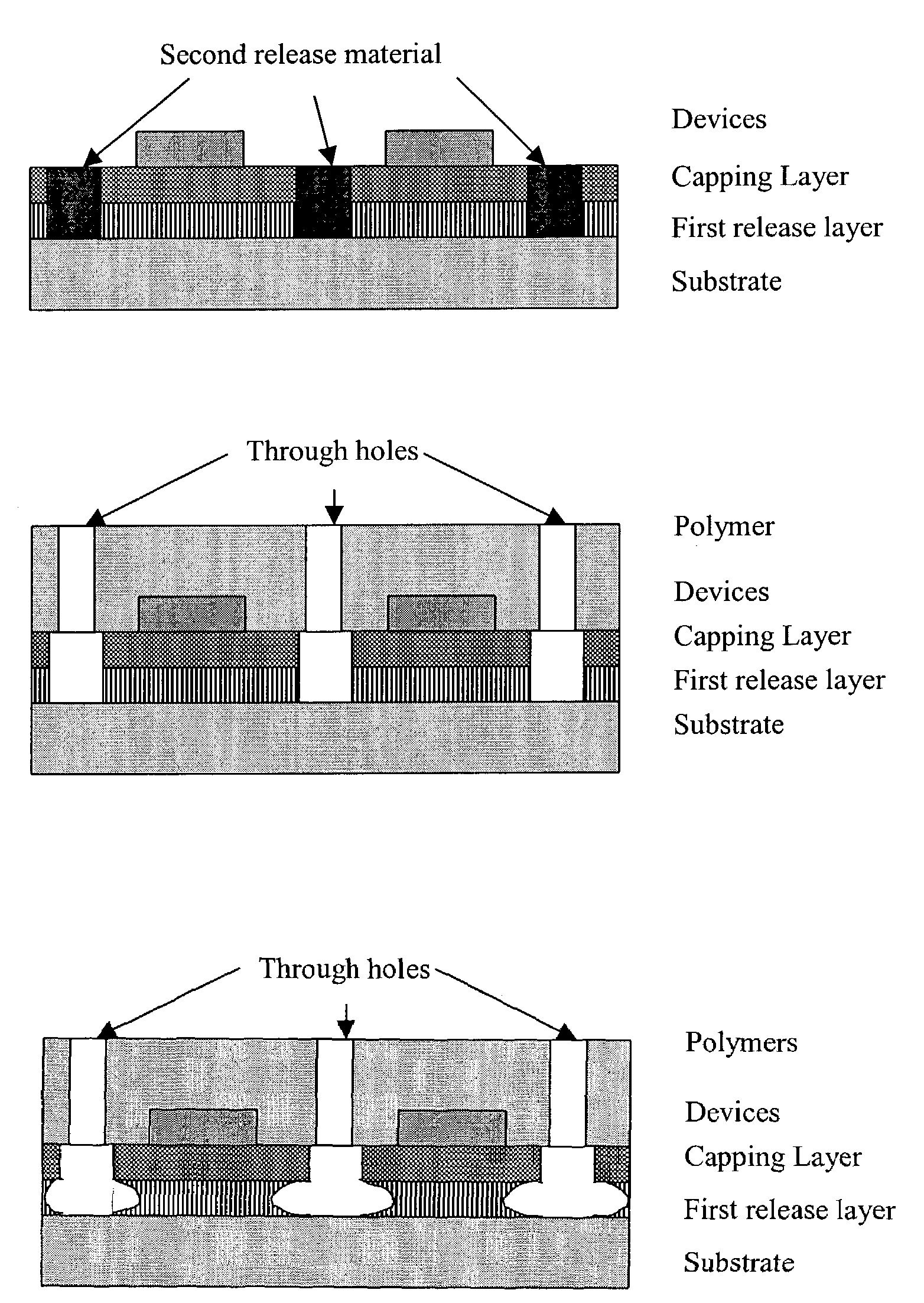
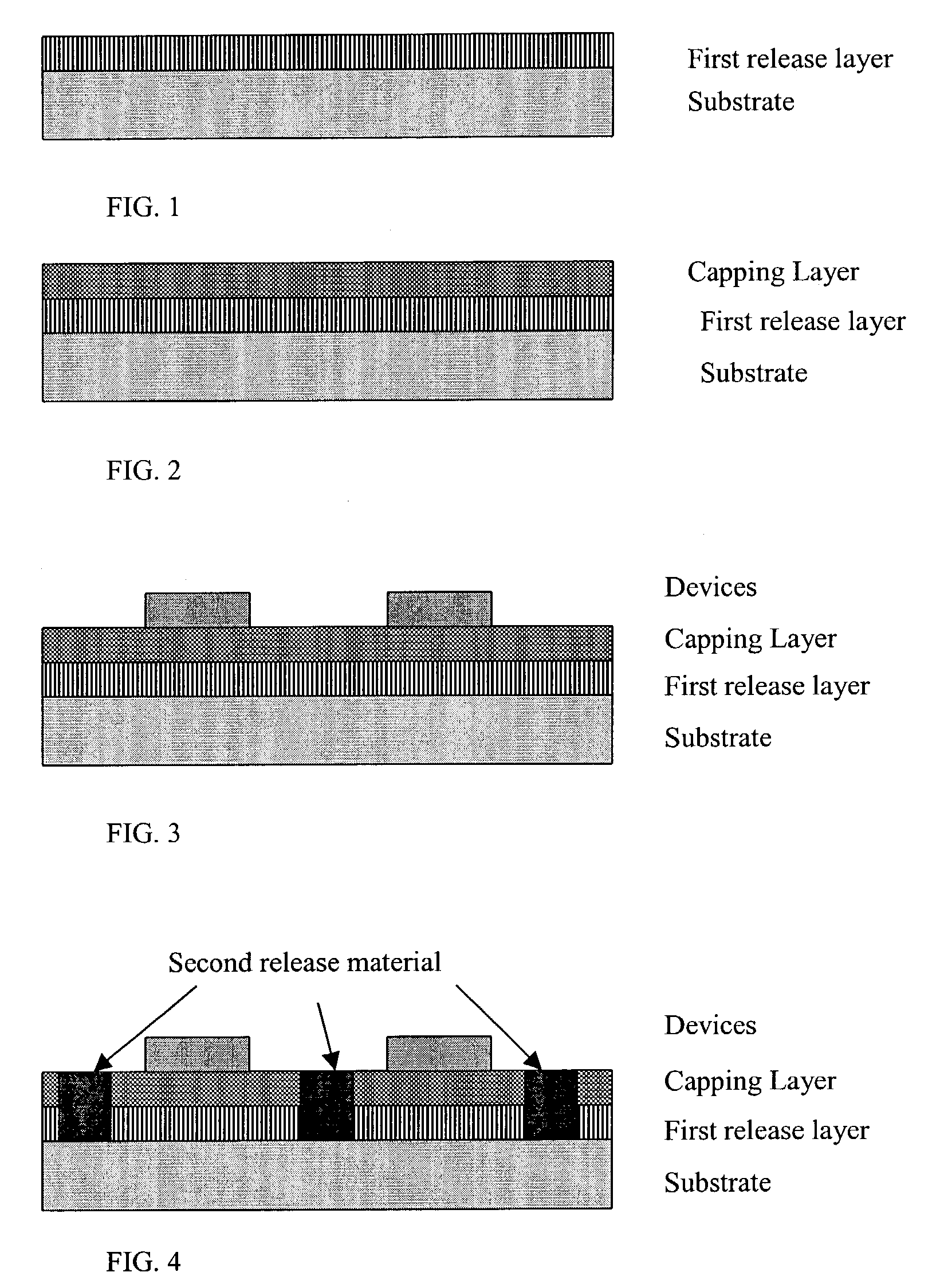
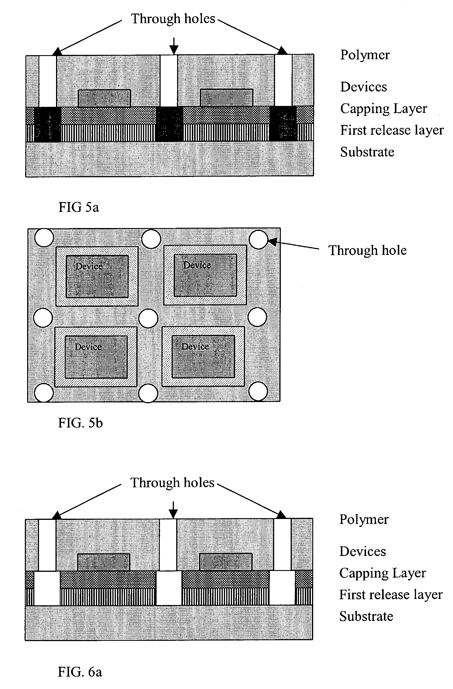
[0068]FIGS. 1-8 illustrate an examplary process flow using a vertical access scheme for the removal process. FIG. 1 depicts a sacrificial (first release) layer deposited on a smooth, “mother” substrate such as glass, quartz, fused silica, metal sheet, silicon, or any other flat-surfaced material. After deposition on the mother substrate the sacrificial is stabilized with one of the processes mentioned above such as annealing. One or more intermediate layers may be positioned beneath this sacrificial layer, if desired. FIG. 2 illustrates the deposition of a capping layer. This is the layer upon which the system devices will be fabricated (See FIG. 3). It is the first of the “building layers”. All deposition steps may be accomplished by a variety of means including spin-on approaches, physical deposition, chemical deposition, and chemical reactions. This capping layer also protects the sacrificial layer and, in...


PUM

PropertyMeasurementUnit
temperaturesaaaaaaaaaa
surface areaaaaaaaaaaa

Abstract

The invention relates to methods for preparing a removable system on a mother substrate. The method deposits a high surface to volume sacrificial layer on a mother substrate and stabilizes the sacrificial layer by a) removing volatile chemical species in and on the sacrificial layer and / or b) modifying the surface of the layer. The method coats over the sacrificial layer with a capping medium. A system is the fabricated on the capping medium. The method provides through holes to access the sacrificial layer. The method may also apply a top layer onto the system to form a covered system. The invention also includes the step of removing the sacrificial layer to release the system from the mother substrate. Methods of the invention also include selectively removing a portion of the system and capping layers to form void regions defining an array of islands composed of device, structure, or system and capping layer regions, and optionally filling the island-defining void region with a sacrificial material. In such methods the sacrificial material and the high surface to volume sacrificial layer are removed to release the system from the mother substrate. Methods of the invention also include applying a layer to the capping material side of the released system to form a configuration wherein the system is substantially within a bending-stress reduced neutral plane. The systems fabricated according to the invention may be placed on a wide variety of suitable substrates, including flexible substrates.

Description

PRIORITY CLAIM[0001]This application claims benefit under 35 U.S.C. §119 to provisional applications Ser. Nos. 60 / 347,850, 60 / 348,259, 60 / 348,258, all filed Jan. 11, 2002, and 60 / 408,235, filed Sep. 4, 2002; all of which are incorporated herein by reference.GOVERNMENT RIGHTS[0002]The United States Government has rights in this invention under DARPA Grant No. S33615-98-1-5164.FIELD OF THE INVENTION[0003]The invention relates to the use of sacrificial layers to fabricate systems on a mother substrate followed by separation of the system from the mother substrate. More particularly the invention relates to stabilizing the sacrificial layer and fabricating high performance substrates with high temperature processing.BACKGROUND OF THE INVENTION[0004]There is a considerable, growing demand for microelectronic, opto-electronic, photovoltaic, bio-systems, optics systems, and micro-electromechanical systems on insulator substrates and on durable, and even light weight and flexible substrates...

Claims


Application Information

Patent Timeline
Patent Type & Authority Patents(United States)
IPC IPC(8): H01L21/00B81C99/00G02B6/12G02B6/132G02B6/136H01L21/20H01L21/68H01L21/762H01L21/77H01L21/84H01L27/12
CPCB81C99/008G02B6/136H01L21/2007H01L21/568H01L21/6835H01L21/76251H01L24/97H01L27/1214H01L27/1266H01M8/1097G02B6/132Y10S438/96G02B2006/12169G02B2006/12176H01L2221/68318H01L2924/01003H01L2924/01004H01L2924/01013H01L2924/01032H01L2924/01039H01L2924/01057H01L2924/09701H01L2924/19042H01L2924/3025Y02E60/521H01L2924/01005H01L2924/01006H01L2924/01033Y10S438/977H01L2924/12042H05K1/189Y02P70/50Y02E60/50H01L2924/00
Inventor FONASH, STEPHEN J.LI, HANDONGLEE, YOUNGCHULCUIFFI, JOSEPH D.HAYES, DANIEL J.
Owner PENN STATE RES FOUND
Why Eureka
Try Eureka