
Wind speed measurement apparatus and method

a wind speed and measurement method technology, applied in the direction of volume metering, instruments, reradiation, etc., can solve the problems that passive beam scanning would obviously prove less useful, and achieve the effect of reducing the strength of the returned signal and greatly reducing the noise generated by spurious reflections

Active Publication Date: 2007-12-25
QINETIQ LTD
View PDF16 Cites 52 Cited by
  • Summary
  • Abstract
  • Description
  • Claims
  • Application Information

AI Technical Summary

Benefits of technology

[0012]The present invention thus provides a buoyant platform apparatus (i.e. a platform that will float on water) that can be quickly and easily deployed at any desired location in an expanse of water and can provide reliable wind speed measurements. In particular, the buoyant platform may be readily deployed off-shore. The present invention thus overcomes the need to construct towers rising from the sea-bed on which conventional anemometers are mounted, and allows the wind profiles of potential off-shore wind farm sites to be assessed at a much lower cost than previously possible. Furthermore, the apparatus of the present invention not only meets the needs of the wind power industry but could also replace wind data collection systems as used, for instance, in the oil and gas industry and in meteorological forecasting.
[0015]The present invention thus provides a wind velocity measurement apparatus mounted on or in a buoyant platform that can provide reliable data on the wind velocity at absolute positions in space. Advantageously, wind velocity measurements acquired from remote probe volumes at a plurality of absolute positions allow a true wind velocity vector to be determined in a given region of space (e.g. at the potential location of a wind turbine).
[0025]Advantageously, the lidar is bistatic. Bistatic lidar systems derive their name from having separate transmit and receive optics. Monostatic lidar systems are also known and are so called because they have common transmit and receive optics. The non-parallel transmit and receive beams of a bistatic system are particularly advantageous because they can be arranged to intersect at a certain point thereby accurately defining the remote probe volume (i.e. the area in space from which Doppler wind speed measurements are acquired). Although confinement of the probe volume may lead to a reduction in the strength of the returned signal for distributed targets, the noise generated by spurious reflections is greatly reduced compared with monostatic systems.

Problems solved by technology

Passive beam scanning would obviously prove less useful when there is little or no platform (e.g. wave) motion, however this typically corresponds to occasions when there is less wind and the data during such periods is usually of least interest.

Method used


Image

  • Wind speed measurement apparatus and method
  • Wind speed measurement apparatus and method
  • Wind speed measurement apparatus and method

Examples


Embodiment Construction

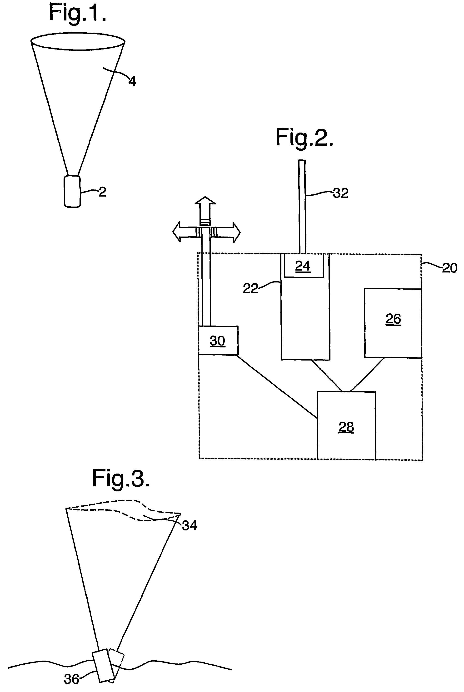
[0038]Referring to FIG. 1, a prior art lidar 2 is shown. The lidar system has a transmit beam and a receive beam that overlap so as to define a certain probe volume in space. The lidar 2 is arranged such that the remote probe volume performs a conical scan 4 thereby allowing the wind velocity to be intersected at a range of angles enabling the true velocity vector to be deduced for a region in space. Other scanning patterns are known and can be used to determine the true wind velocity vector, provided that the lidar range and pointing (or look) direction is always known with a sufficient degree of accuracy. Such lidar systems have been used to measure wind shear, turbulence and wake vortices for many years in both military and civil applications.

[0039]To make reliable wind speed measurements in fixed regions in space (i.e. in a fixed region relative to the ground) prior art lidar systems are secured in position and scanning means are provided to alter the look direction of the lidar...


PUM


Abstract

A buoyant platform apparatus, such as a buoy, is described that comprises a laser radar (lidar) wind speed measurement device. The lidar is arranged to make wind velocity measurements at one or more remote probe volumes of known position relative to said platform. The wind speed measurement apparatus may further comprise motion sensing means that, in use, monitor motion of the platform allowing wind speed at an absolute position in space to be measured. Wind velocity data may also be compensated for platform movement.

Description

BACKGROUND OF THE INVENTION[0001](1) Field of the Invention[0002]This invention relates to a method and apparatus for wind speed measurements using a laser radar (lidar) wind speed measurement system. More particularly, the invention relates to wind speed measurement apparatus for use on floating platforms such as buoys.[0003](2) Description of the Art[0004]At present, there is much interest in the exploitation of renewable energy resources in an attempt to reduce the greenhouse gases produced by burning fossil fuels. One type of renewable energy resource that has received much attention is wind power.[0005]Land based wind farms comprising a number of wind turbines have been used commercially to produce energy for many years. However, finding sites that are suitable for such wind farms has proved problematic, especially in the light of local environmental objections. Recently, this has led to the development of off-shore wind farms where the environmental impact is greatly reduced. ...

Claims


Application Information

Patent Timeline
IPC IPC(8): G01F13/00G01S17/58G01S17/95
CPCG01S17/58G01S17/95G01S17/023G01S17/003G01S17/86Y02A90/10
Inventor SMITH, DAVID ARTHURHARRIS
Owner QINETIQ LTD
Learn More