Supported catalyst systems

a catalyst system and catalyst technology, applied in the field of supported catalyst systems, can solve the problems of leaving them catalytically inactive, and achieve the effects of reducing the ability to non-specifically, reducing the ability to hydrophobic interactions, and reducing the ability to electrostatic interactions

Inactive Publication Date: 2008-01-01
WR GRACE & CO
View PDF89 Cites 0 Cited by
  • Summary
  • Abstract
  • Description
  • Claims
  • Application Information

AI Technical Summary

Benefits of technology

[0015]Accordingly, it is an advantage of the present invention to provide improved supported catalyst systems wherein the support has a reduced ability to non-specifically bind to unwanted non-catalytic materials.
[0016]Another advantage of the present invention is to provide supported catalyst systems wherein the support has no or substantially no surface charge at the operating pH of adsorption and is hydrophilic in nature.
[0017]It is yet another advantage of the present invention to provide supported catalyst systems wherein the support has a reduced ability for hydrophobic interactions.
[0018]Another advantage of the present invention is to provide supported catalyst systems wherein the support has a reduced ability for electrostatic interactions.
[0019]Another advantage of the present invention is to provide supported catalyst systems wherein the support has a reduced ability for both electrostatic and hydrophobic interactions, thereby maintaining a low enthalpy of adsorption.
[0020]Another advantage of the present invention is to provide inorganic oxide supported catalyst systems, which resists nonspecific binding.

Problems solved by technology

Moreover, avoiding a surface charge reduces or prevents the strong attractive electrostatic forces, which can denature certain catalytic species, such as enzymes or organometallic complexes, leaving them catalytically inactive.

Method used


Image

  • Supported catalyst systems
  • Supported catalyst systems
  • Supported catalyst systems

Examples


examples 1 and 2

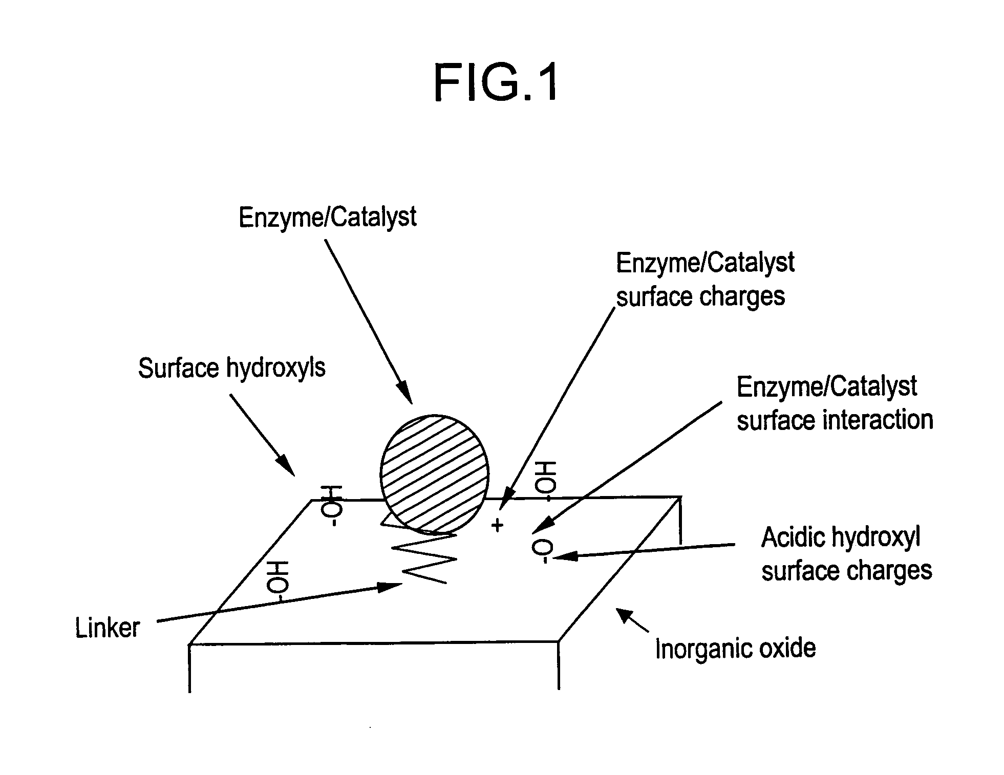
Non-Specific Binding on Conventional Silica Media

[0127]These examples show that the neat uncoated charged silica surface of the prior art strongly adsorbs proteins based mostly on isoelectric point and the surface area of the silica. Two types of silicas were tested: Examples 1 and 2.

[0128]Example 1 is a low surface area silica gel with a surface area=161 m2 / g after 4 hours at 150° C. heat treat (micropore=73 m2 / g; mesopore=88 m2 / g; pore volume=0.373 cc / g; average pore diameter=93 Å).

[0129]Example 2 is a higher surface area / pore volume silica gel, surface area=253 m2 / g after 4 hours at 150° C. heat treat (micropore=35 m2 / g; mesopore=218 m2 / g; pore volume=2.445 cc / g; average pore diameter=387 Å).

[0130]The examples below describe a procedure wherein the neat silica samples of Examples 1 and 2 were contacted with a complex mixture of proteins in aqueous solution. The resultant supernatant was then analyzed by isoelectric focusing gel electrophoresis for protein adsorption.

[0131]A vial ...

examples 3-5

Non-Selective Binding on Hydrophobic Supports

[0134]These examples show that when silica is coated with hydrophobic groups, or methyl or octyl groups, strong adsorption occurs, especially at moderate ion strength of the solvent (approximately 0.1 M NaCl).

[0135]The support of Example 3 is an uncoated neat commercial wide pore silica from W. R. Grace & Co., XWP-gel P 005, SA=72 m2 / g, with 50 nm pore median that had been activated for 2 hours at 150° C.

[0136]The support of Example 4 is the silica of Example 3 coated with methyl groups as described below.

[0137]The support of Example 5 is the silica of Example 3 coated with octyl groups as described below.

[0138]The support of Example 4 was prepared as follows: in a 250 ml round bottom flask, 50 ml toluene and 6.16 g of methyltriethoxysilane were added. Then 10.1 g of the silica of Example 3 were added to the toluene / methyltriethoxysilane solution. N2 was flowed for 5 minutes to remove air and continued for the entire reaction. The sample ...

examples 6-8

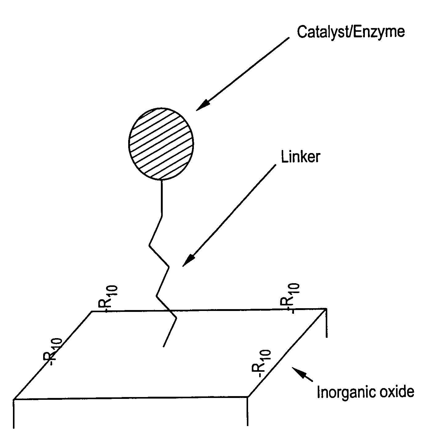
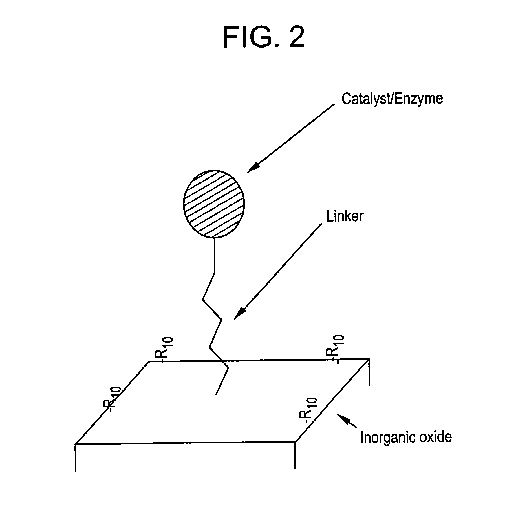
Reducing Non-Selective Binding using an R10 Group

[0147]Examples 6-8 show the advantage of employing an R10 group according to the invention for reducing non-selective protein binding to a silica surface.

[0148]The support of Example 6 is the same as the silica of Example 3 except the silica was activated for 2 hours at 200° C.

[0149]The support of Example 7 is an intermediate surface composition, with the silica surface having Si—R groups attached, wherein R is acetoxymethyl.

[0150]The support of Example 8 is an example of the surface composition of the present invention, with the silica surface having Si—R10 groups attached, wherein R10 is methylhydroxy. The advantage of the surface of the support of Example 8 with high and low ionic strength solvents is also shown.

[0151]The support of Example 7 was prepared as follows: in a 250 ml round bottom flask, 50 ml toluene and 20.42 g of acteoxymethyltriethoxysilane were added. 15.05 g of the support of Example 6 were added to the toluene / act...


PUM

PropertyMeasurementUnit
surface areaaaaaaaaaaa
hydrodynamic radiusaaaaaaaaaa
frequencyaaaaaaaaaa

Abstract

The present invention relates to a supported catalyst system. The supported catalyst of the present invention comprises an inorganic support having attached to at least one surface thereof non-acidic, hydrophilic, hydroxyl-containing organic R10 groups having no or substantially no surface charge in solution, and at least one linker capable of binding a catalytic species, e.g. an enzyme or an organometallic molecule, wherein the linker is attached to a catalytic species. The R10 groups preferably are selected from the group consisting of —CH2OH, —CH(OH)2, —CH(OH)CH3, —CH2CH2OH, —CH(OH)2CH3, —CH2CH(OH)2, —CH(OH)CH2(OH) and mixtures thereof. The presence of the R10 groups on the support surface prevents or reduces non-specific binding of the catalytic species with the support surface by minimizing hydrophobic interactions and providing no or substantially no surface charge in the region of the support having catalytic species attached thereto. Simultaneously, the linker binds the catalytic species to the surface of the support in a manner which permits the catalytic species to be freely available for catalytic activity. Methods of catalyzing a reaction using the supported catalyst system of the invention are also disclosed.

Description

RELATED APPLICATIONS[0001]This application is a division of U.S. Ser. No. 10 / 357,115, filed Feb. 3, 2003, now U.S. Pat. No. 6,987,079, which, in turn is a continuation-in-part of U.S. application Ser. No. 09 / 929,621 filed Aug. 14, 2001, now U.S. Pat. No. 6.802,966 the contents of which are incorporated by reference herein.FIELD OF THE INVENTION[0002]The present invention is directed to novel catalyst systems, and the use thereof in catalysis. More specifically, the present invention relates to supported catalyst systems having at least one catalytic species, e.g. an enzyme or organometallic complexes, immobilized or attached on at least one surface of a support, which surface has been modified to prevent non-specific binding of the catalytic species to the support. The catalyst systems exhibit high catalytic activity and permits easy separation and recovery of the catalytic species for reuse.BACKGROUND OF THE INVENTION[0003]The synthesis of fine chemicals and pharmaceuticals has bec...

Claims


Application Information

Patent Timeline
Patent Type & Authority Patents(United States)
IPC IPC(8): B01J31/00B01J20/281G01N30/50B01J20/283B01J20/284B01J20/288B01J20/289B01J20/32B01J31/02B01J31/16C12M1/00C12N11/14C12N15/09C12P13/00C12P13/22C12P21/06C12Q1/68G01N30/02G01N30/88
CPCB01J31/003B01J31/1633C12N11/14C12P13/222C12P21/06B01J31/0254Y10S502/523B01J2219/00605B01J2219/00612B01J2219/00626B01J2219/00637B01J2219/00641B01J2219/00644B01J2220/54B01J2231/40B01J2231/4211B01J2231/4261G01N30/02B01D15/3804Y02P20/50B01J31/00B01J20/30
Inventor WORMSBECHER, RICHARD FRANKLIN
Owner WR GRACE & CO
Why Eureka
Try Eureka