
Light integration unit, optical pickup device using the unit, and optical disk device

Active Publication Date: 2008-01-01
SHARP KK
View PDF22 Cites 4 Cited by
  • Summary
  • Abstract
  • Description
  • Claims
  • Application Information

AI Technical Summary

Benefits of technology

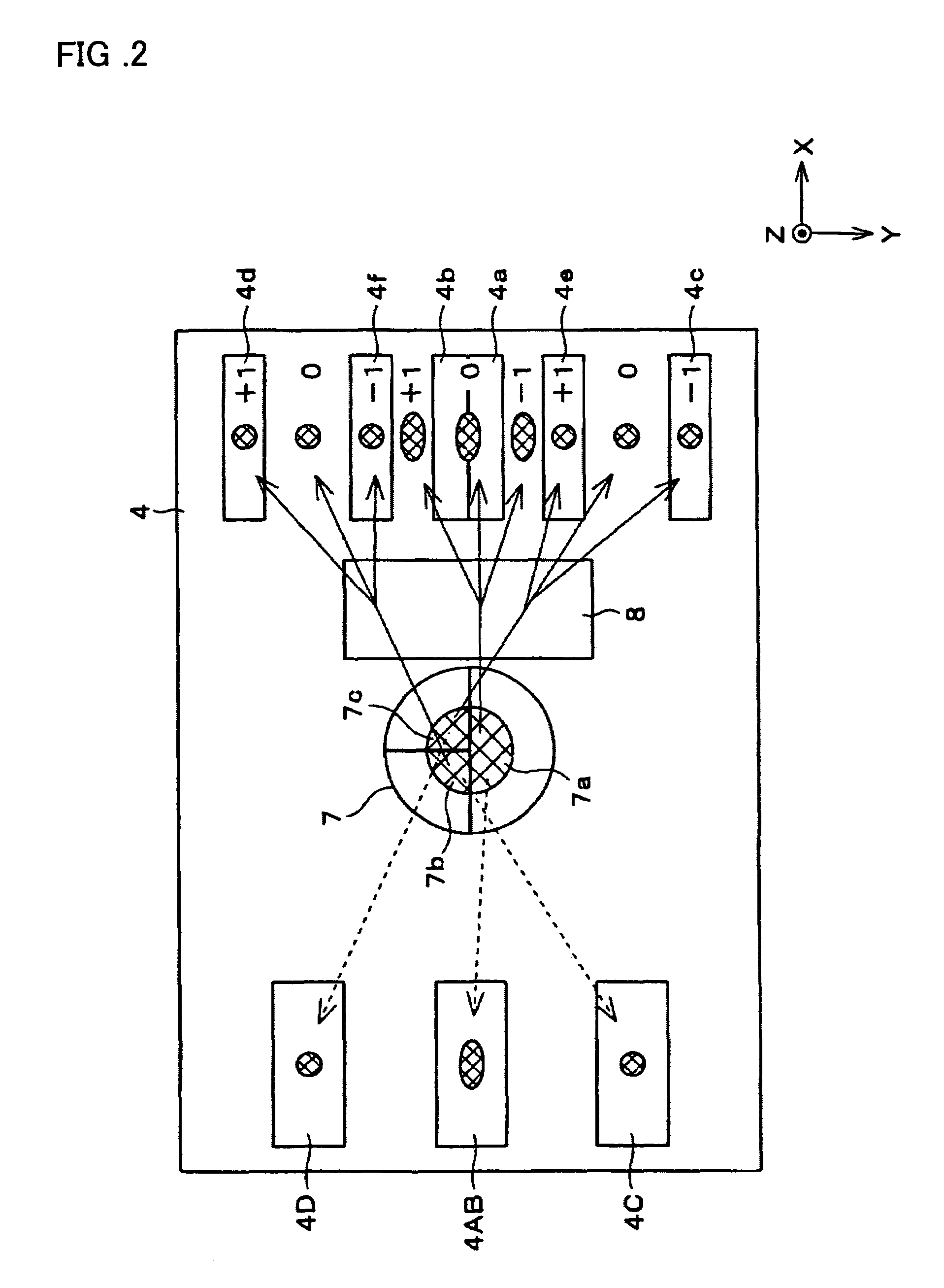
[0017]In this configuration, in employing a one-beam tracking method in which a quantity of recording light and thereby a recording speed can be increased by irradiation of a single laser beam onto the information recording medium having the disk shape, the optical element is provided between the hologram, which is used to obtain a diffracted light beam for tracking, and the light receiving section, and the transmittance of the optical element is varied in the disk radial direction.
[0077]With this configuration, it is possible to provide an optical disk device that is compatible with disks of different specifications without changing the configuration of the pickup, and that can reduce an offset caused by a shift of the object lens regardless of the type of disk in performing the recording and reproduction.

Problems solved by technology

Therefore, shifting of the object lens is also caused by disk decentering.
A track error is detected from a differential signal of the sub beams.
As a result, there is a problem that a recording speed slows, and a high-speed recording is hindered accordingly.

Method used


Image

  • Light integration unit, optical pickup device using the unit, and optical disk device
  • Light integration unit, optical pickup device using the unit, and optical disk device
  • Light integration unit, optical pickup device using the unit, and optical disk device

Examples


Embodiment Construction

[0100]One embodiment of the present invention is described below with reference to the attached drawings.

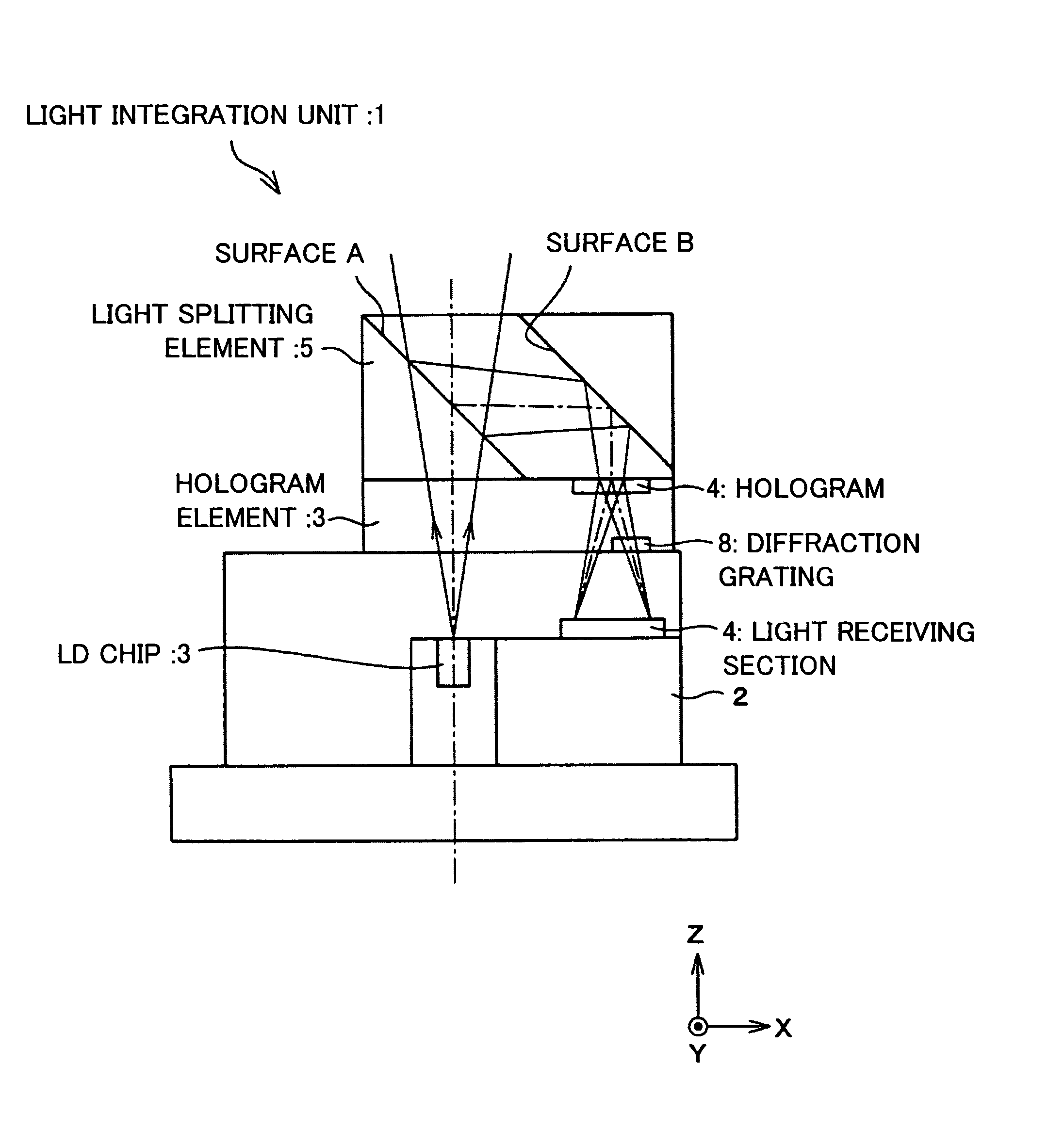
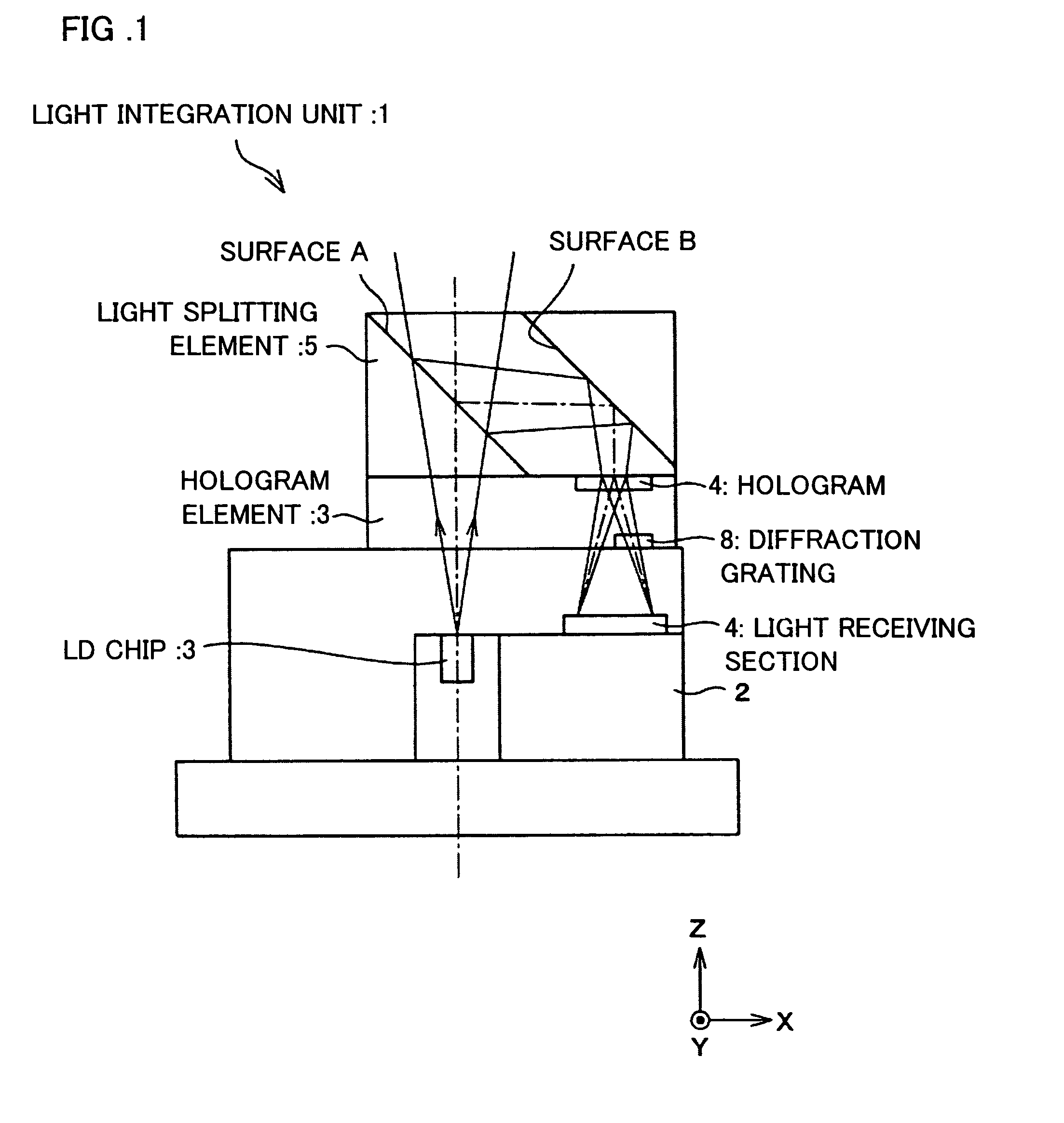
[0101]FIG. 1 is a cross-sectional view illustrating a schematic configuration of a light integration unit 1 of the present invention. The light integration unit 1 constitutes an optical pickup device for DVD, by being combined with an object lens means for focusing, onto a disk, a laser beam emitted from the light integration unit 1. Schematically, the light integration unit 1 includes an LD (Laser Diode) chip 3 mounted to a stem 2, a light receiving section 4, a light splitting element 5, and a hologram element 6.

[0102]The LD chip (light emitting section) 3 emits a laser beam onto, for example, a DVD (Digital Versatile Disc, Digital Video Disk), which is an information recording medium having a disk shape. The light splitting element 5 reflects, for example, reflected light from the DVD into a hologram 7 of the hologram element 6. The hologram 7 diffracts light from the light sp...


PUM


Abstract

An object of the present invention is to attain stable tracking servo performance by suppressing an offset caused by a shift of an object lens or a tilt of a disk, despite the one-beam method which does not cause reduction in light quantity of the main beam. A diffraction grating is provided between a hologram and a light receiving section, and a diffraction efficiency of the diffraction grating is varied in a grating longitudinal direction. For example, if an incident light beam on the diffraction grating is shifted in the grating longitudinal direction, the quantity of received light in each light receiving section varies to cause offset. By performing tracking servo so as to cancel the change, it is possible to correct the offset, thereby attaining stable tracking servo performance.

Description

[0001]This application claims priority from PCT international application No. PCT / JP02 / 11538 filed Nov. 5, 2002, which in turn claims priority from Japanese application No. 2001-345072 filed Nov. 9, 2001, Japanese application No. 2002-115922 filed Apr. 18, 2002, and Japanese application No. 2002-248479 filed Aug. 28, 2002, the disclosures of all of which are incorporated herein by reference.TECHNICAL FIELD[0002]The present invention relates to a light integration unit used in an optical disk device for optically recording or reproducing information by using an information recording medium such as an optical disk, and relates to an optical pickup device and optical disk device using such a light integration unit.BACKGROUND ART[0003]In order to realize a smaller, thinner, and more reliable optical pickup device, such an optical pickup device that uses a hologram has been devised. A basic configuration of such an optical pickup device for DVDs (Digital Video Disks) is described in Japa...

Claims


Application Information

Patent Timeline
IPC IPC(8): G11B7/135G11B7/1353G11B7/09
CPCG11B7/0901G11B7/094G11B7/1205G11B7/131G11B7/1353G11B7/123G11B7/09
Inventor SAKAI, KEIJIMIYAKE, TAKAHIROUEYAMA, TETSUOMIKI, RENZABUROMAKIOKA, HIROSHIGEFUJITA, NOBORUMIYAZAKI, OSAMU
Owner SHARP KK
Learn More