Devices and methods for implanting fusion cages

a fusion cage and cage technology, applied in the field of spinal stabilization surgery, can solve the problems of implant migration into the vertebral body, the above-mentioned devices do not adequately address the problem of restoring and maintaining the normal anatomy of the fused spinal segment, and the posterior portion over-reaming is generally not well accepted

Inactive Publication Date: 2008-01-08
WARSAW ORTHOPEDIC INC
View PDF58 Cites 70 Cited by
  • Summary
  • Abstract
  • Description
  • Claims
  • Application Information

AI Technical Summary

Benefits of technology

[0017]Yet another aspect of the present invention is to provide a fusion cage for insertion in an unreamed disc space. The cage includes a body having a hollow interior extending between a trailing end and a leading end. In one form, the body is threaded and tapered to restore lordosis when inserted in the disc space. The cage has a top surface and a bottom surface positioned in contact with the intact endplates of the vertebrae when the cage is implanted. The body defines a number of openings in the top and bottom surface. Preferably, external threads extend outwardly from the body portion and engage the cage to the bony end plates and harvest disc material and bone from the endplates for deposit through the openings into the hollow interior. In another form, the fusion cage is provided with threads with a swept back profile that increase in depth from the leading end to the trailing end to prevent backout of the inserted cage from the disc space.
[0018]One aspect of the invention contemplates providing an interbody fusion cage or device having opposed upper and lower bearing surfaces separated by a height. In one form, the height tapers along the length of the device to match angulation between endplates of adjacent vertebra. In a preferred form, the device includes migration resistance structures intended to limit movement of the fusion device in the disc space. Preferably, these migration resistance structures may include threads, ridges, knurling, spikes, or other surface irregularities extending from the bearing surface. One improvement of interbody fusion devices according to the present invention can be characterized as the spacing distance being substantially equal to the distance between unreamed endplates of adjacent vertebra thereby eliminating the need for removing vertebral endplate bone to form an insertion channel.
[0020]In one preferred form, the fusion cage is inserted into a disc space having intact endplates. In another preferred form, a cutting instrument is provided that is inserted through the cage and configured to remove endplate bone material through the at least one opening. In one form, the cutting instrument includes a burr for removing bony material. In another form, the cutting instrument includes a curette for removing bony material. In yet another form, the cutting instrument is configured to remove bony material simultaneously from laterally adjacent holes through the fusion cage. In another preferred form, the fusion cage includes a guide at the trailing end of the cage opposite the at least one hole for the maintaining the cutting instrument alignment and facilitating use of the cutting instrument in the fusion cage.

Problems solved by technology

One problem that is not adequately addressed by the above prior devices concerns restoring and maintaining the normal anatomy of the fused spinal segment.
However, for a cylindrical implant, the over-reaming of the posterior portion is generally not well accepted because of the extensive removal of load bearing bone of the vertebrae.
Over time, the implant tends to migrate into the vertebral bodies since the load-bearing surfaces of the endplates are no longer adequate for the implant to support the spinal column loads.
When an implant subsides into adjacent bone, the disc space can collapse, resulting in potentially adverse consequences to the patient's health.
Another problem is that when the disc space and adjacent endplates are reamed, the implant must have a height greater than that of the original disc space height to restore the disc space to its normal anatomy.
This positions the larger implants closer to the medial portion of the disc space and vertebral endplates, thus increasing the risk of migration into the vertebral bodies and subsidence of the spinal column around the implant.

Method used


Image

  • Devices and methods for implanting fusion cages
  • Devices and methods for implanting fusion cages
  • Devices and methods for implanting fusion cages

Examples


Embodiment Construction

[0063]For the purposes of promoting an understanding of the principles of the invention, reference will now be made to the embodiments illustrated in the drawings and specific language will be used to describe the same. It will nevertheless be understood that no limitation of the scope of the invention is thereby intended. Any such alterations and further modifications in the illustrated devices, and any such further applications of the principles of the invention as illustrated therein are contemplated as would normally occur to one skilled in the art to which the invention relates.

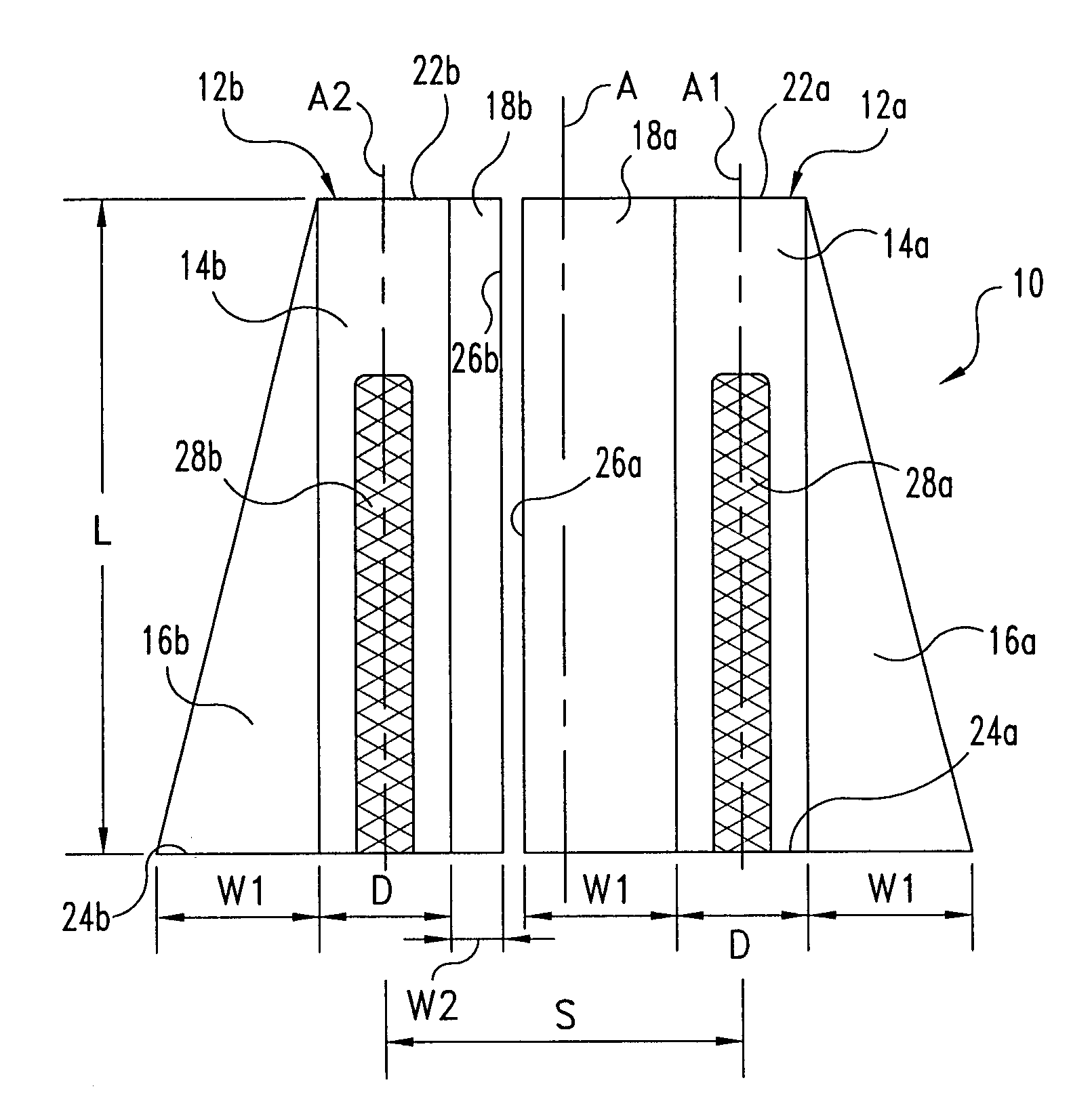
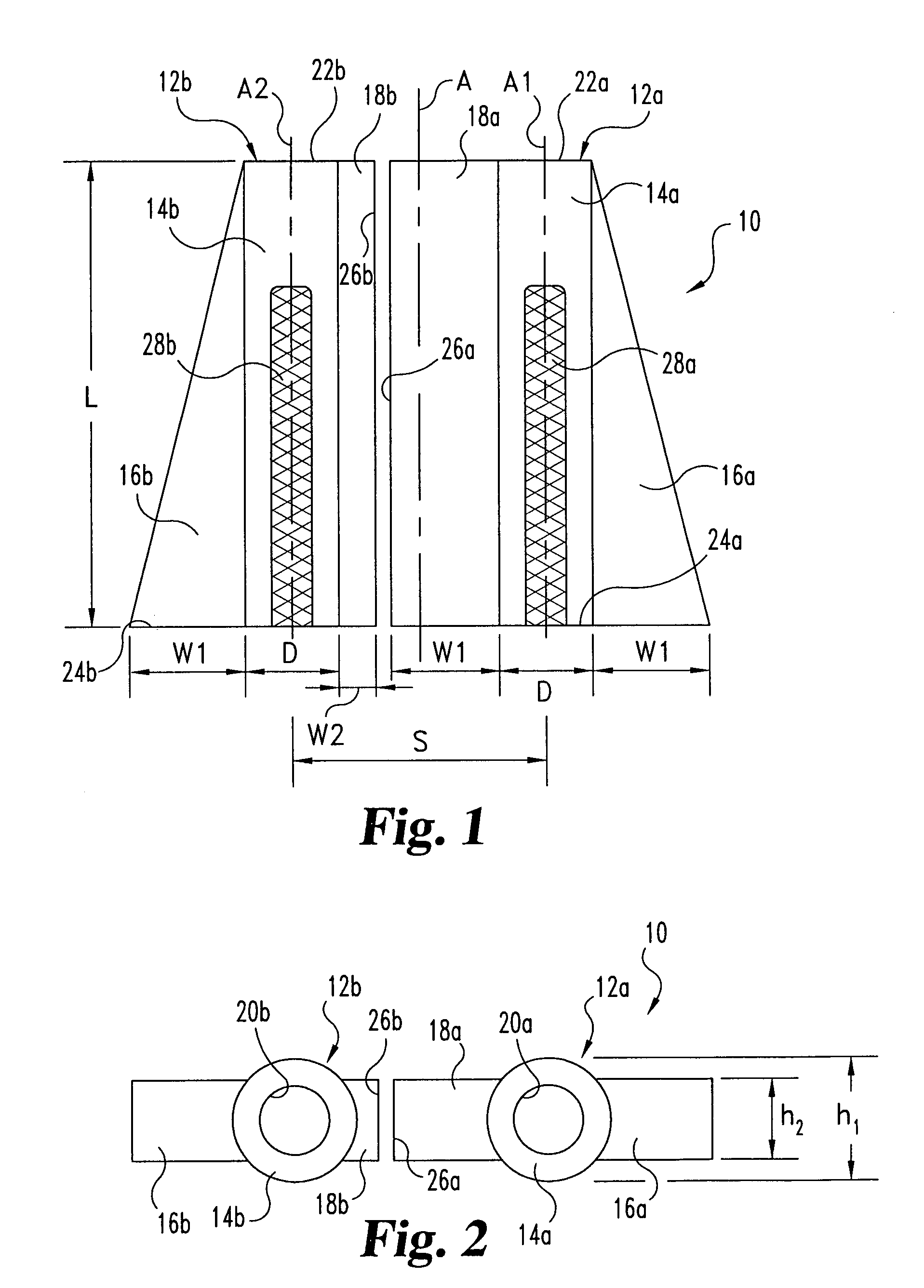
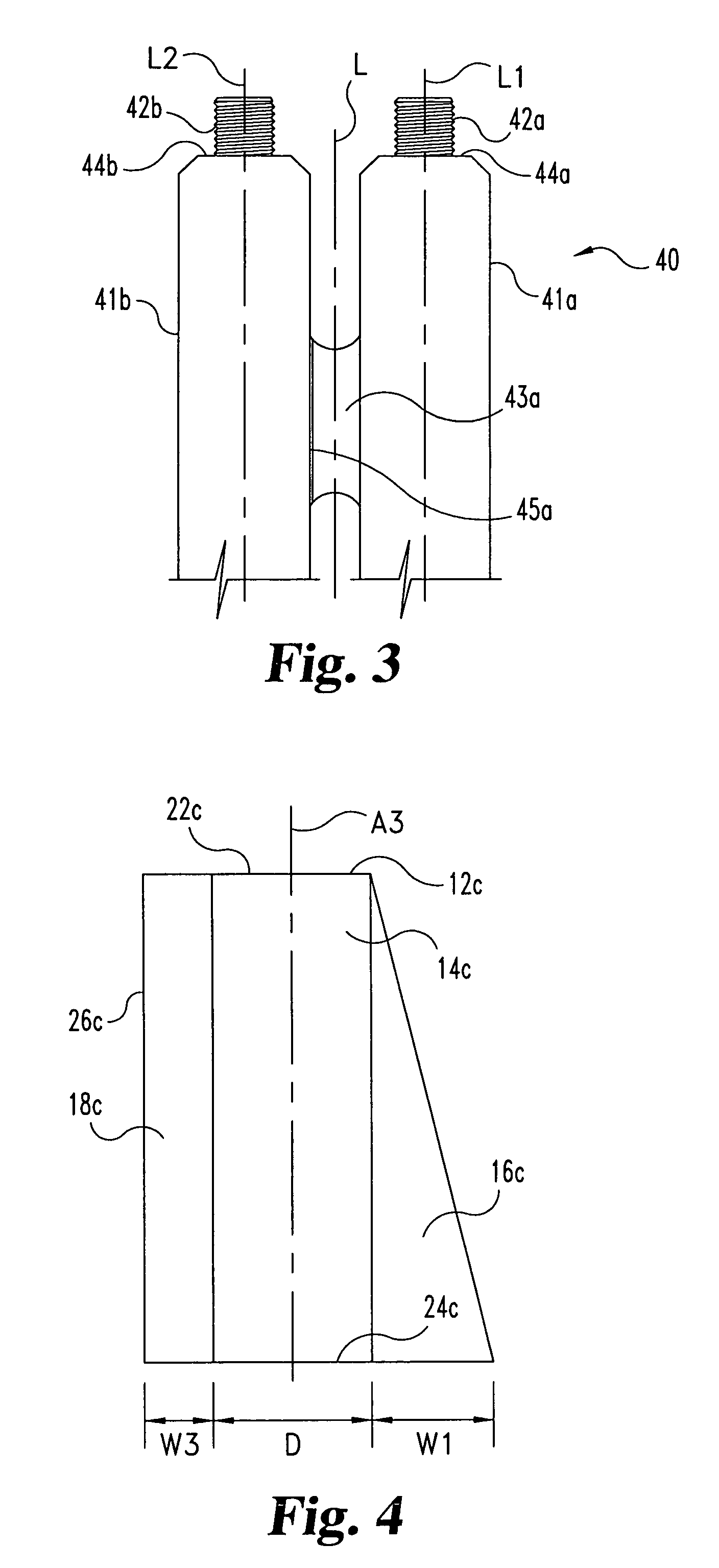
[0064]The present invention relates generally to instruments, devices, and methods for performing vertebral interbody fusion. While it should be understood that the instruments and devices disclosed herein have many uses, it is particularly contemplated that they may be used to perform vertebral interbody fusion in an unreamed disc space with the endplates remaining completely or substantially intact. It...


PUM


Abstract

Methods and instrumentation for spinal interbody fusion are disclosed. The instruments and methods are particularly adapted for interbody fusion in an unreamed disc space. One instrument is a distractor assembly including a first distractor and a second distractor configured to be inserted in side-by-side relation in the disc space. Fusion cages adapted for insertion into an unreamed disc space are provided to enhance load distribution between adjacent vertebral bodies and lateral stability of the spinal column. The fusion cages may be inserted after distracting the disc space with the distractor assembly. Instruments for preparing the disc space through the inserted fusion cages or for use with the distractor assembly are also provided.

Description

CROSS-REFERENCE TO RELATED APPLICATIONS[0001]The present application is a continuation of U.S. patent application Ser. No. 09 / 649,696, filed Aug. 28, 2000, and now issued as U.S. Pat. No. 6,723,096; which claims the benefit of the filing date of Provisional application Ser. No. 60 / 150,787, filed Aug. 26, 1999, entitled DEVICES AND METHODS FOR IMPLANTING FUSION CAGES. The referenced applications are incorporated herein by reference in their entirety.BACKGROUND OF THE INVENTION[0002]The present invention relates generally to surgical procedures for spinal stabilization, and more specifically to instrumentation and techniques for inserting a spinal implant within the intervertebral disc space between adjacent vertebra. More particularly, while aspects of the present invention may have other applications, the invention provides instruments, techniques, and implants especially suited for implanting one or more fusion cages in an unreamed disc space.[0003]There have been an extensive numb...

Claims


Application Information

Patent Timeline
Patent Type & Authority Patents(United States)
IPC IPC(8): A61F2/28A61B17/02A61B17/16A61B17/17A61B17/32A61B19/00A61F2/00A61F2/30A61F2/44A61F2/46
CPCA61B17/025A61B17/1659A61B17/1671A61F2/4455A61F2/446A61F2/4611A61B17/1757A61B17/32002A61B2017/0256A61B2019/306A61F2/30744A61F2/442A61F2002/2817A61F2002/2835A61F2002/3021A61F2002/30217A61F2002/30405A61F2002/30774A61F2002/30777A61F2002/30785A61F2002/30787A61F2002/30789A61F2002/3082A61F2002/30858A61F2002/30861A61F2002/30874A61F2002/4475A61F2002/448A61F2002/4627A61F2220/0025A61F2230/0067A61B2090/036A61F2002/30873A61F2002/30593
Inventor DORCHAK, JOHN D.BURKUS, J. KENNETHRAY, III, EDDIE F.WHITE, JOHN L.
Owner WARSAW ORTHOPEDIC INC
Why Eureka
Try Eureka