
Method and apparatus for blocking radiographic scatter

a radiographic scatter and apparatus technology, applied in the field of medical imaging systems, can solve problems such as image degradation of scatter related images, and achieve the effects of reducing scatter composite imaging information, improving scatter compensation, and further enhancing scatter performan

Inactive Publication Date: 2008-01-15
HOLOGIC INC
View PDF10 Cites 26 Cited by
  • Summary
  • Abstract
  • Description
  • Claims
  • Application Information

AI Technical Summary

Benefits of technology

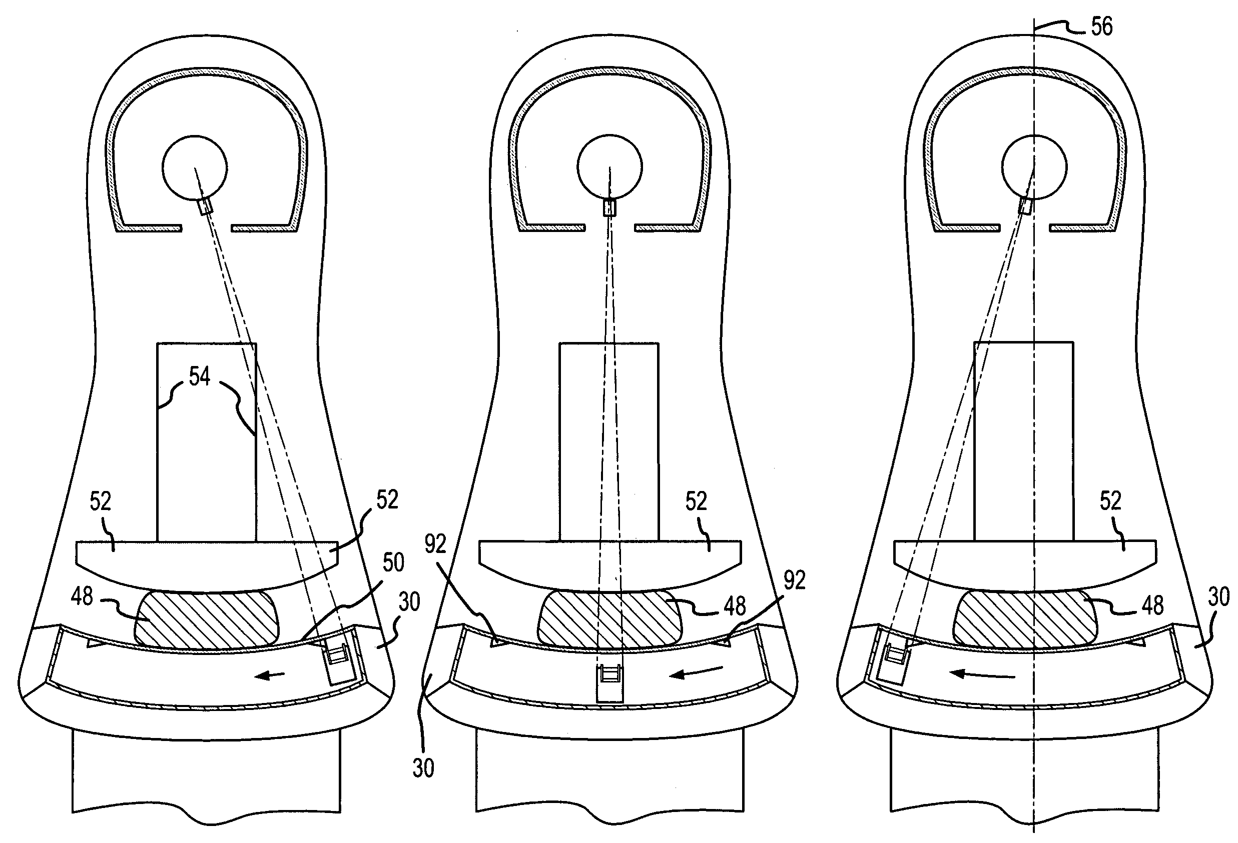
The present invention relates to a radiographic imaging device and method for reducing the effects of scattered radiation or scatter. This is achieved by reducing detected scatter and compensating for scatter that may occur in the imaging process. This improves the contrast and resolution of features being imaged, and can lead to reduced patient dosages and improved detection of low-contrast features. The invention is particularly useful in composite imaging systems that obtain imaging information from different portions of an area of interest at different times. The invention involves selectively blocking photons that are directed to a detector location, while allowing passage of photons associated with a pathway disposed at an angle to the primary imaging signal. The scatter rejection assembly includes a rejection element that is positioned and operated to minimize interference with the desired imaging signal. The invention can be used in various imaging modalities such as mammography and can provide improved image quality and reduced patient dose.

Problems solved by technology

However, it has been recognized that scattered radiation, including single scatter radiation (associated with a single scatter event / interaction) and multiple scatter radiation (associated with more than one scatter event / interaction), associated with Rayleigh and / or Compton scattering, may still impinge on the active detector area, presenting a possibility of scatter related image degradation.

Method used


Image

  • Method and apparatus for blocking radiographic scatter
  • Method and apparatus for blocking radiographic scatter
  • Method and apparatus for blocking radiographic scatter

Examples


Embodiment Construction

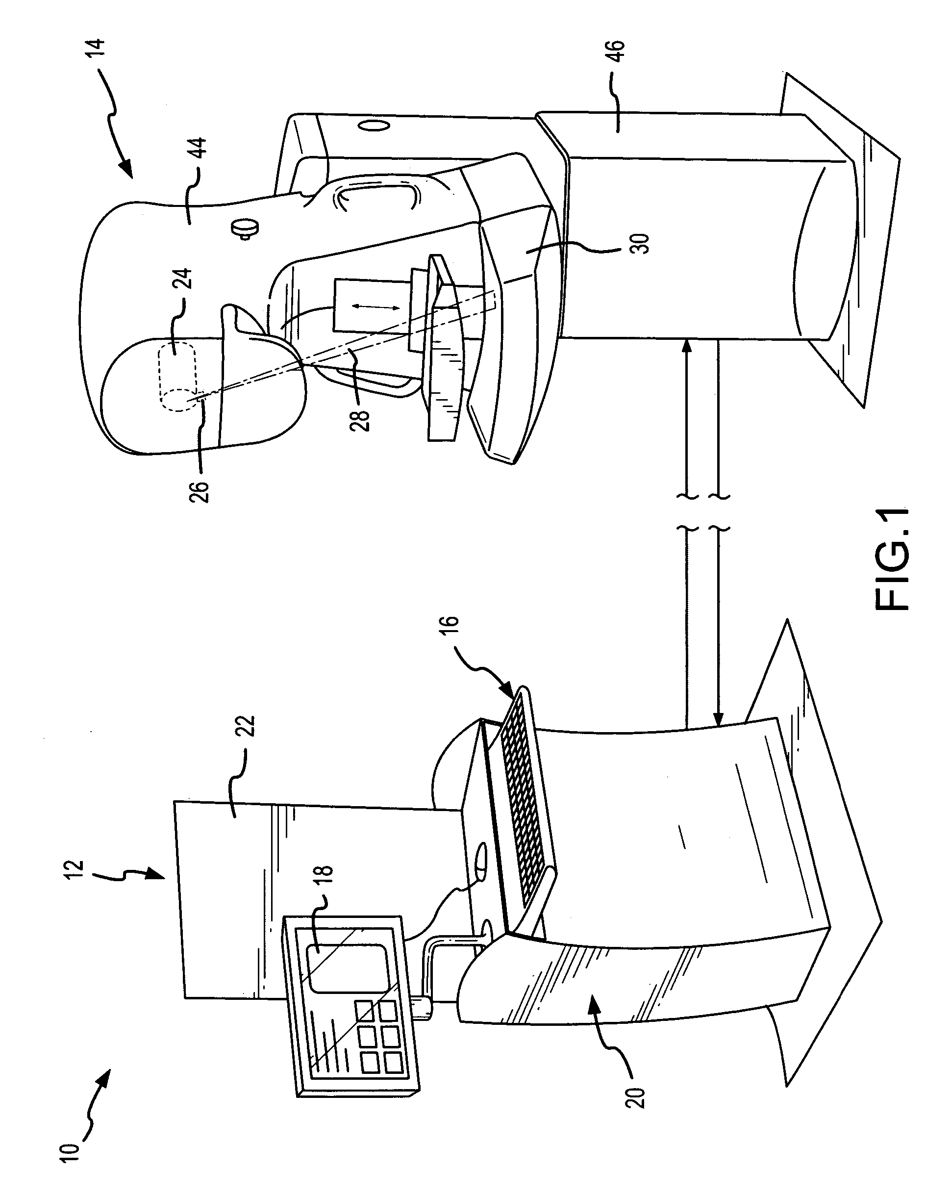
[0039]In the following description, the invention is set forth in the context of a digital, x-ray slot-scan mammography system. This represents a particularly advantageous implementation of the invention as mammography is a challenging medical imaging application, in terms of both required contrast and resolution, and digital slot-scanning provides a number of advantages as discussed above related to reduced scatter, reduced dosage, enhanced resolution and digital display enhancement. However, various aspects of the invention are more broadly applicable in other contexts including other medical imaging applications.

[0040]The following discussion first provides a description of a digital slot-scan mammography system. Thereafter, various system components for reduced scatter generation and improved scatter rejection are described, i.e., system adaptations to reduce the amount of scattered photonic energy detected at a detector surface. Finally, various system adaptations and processin...


PUM


Abstract

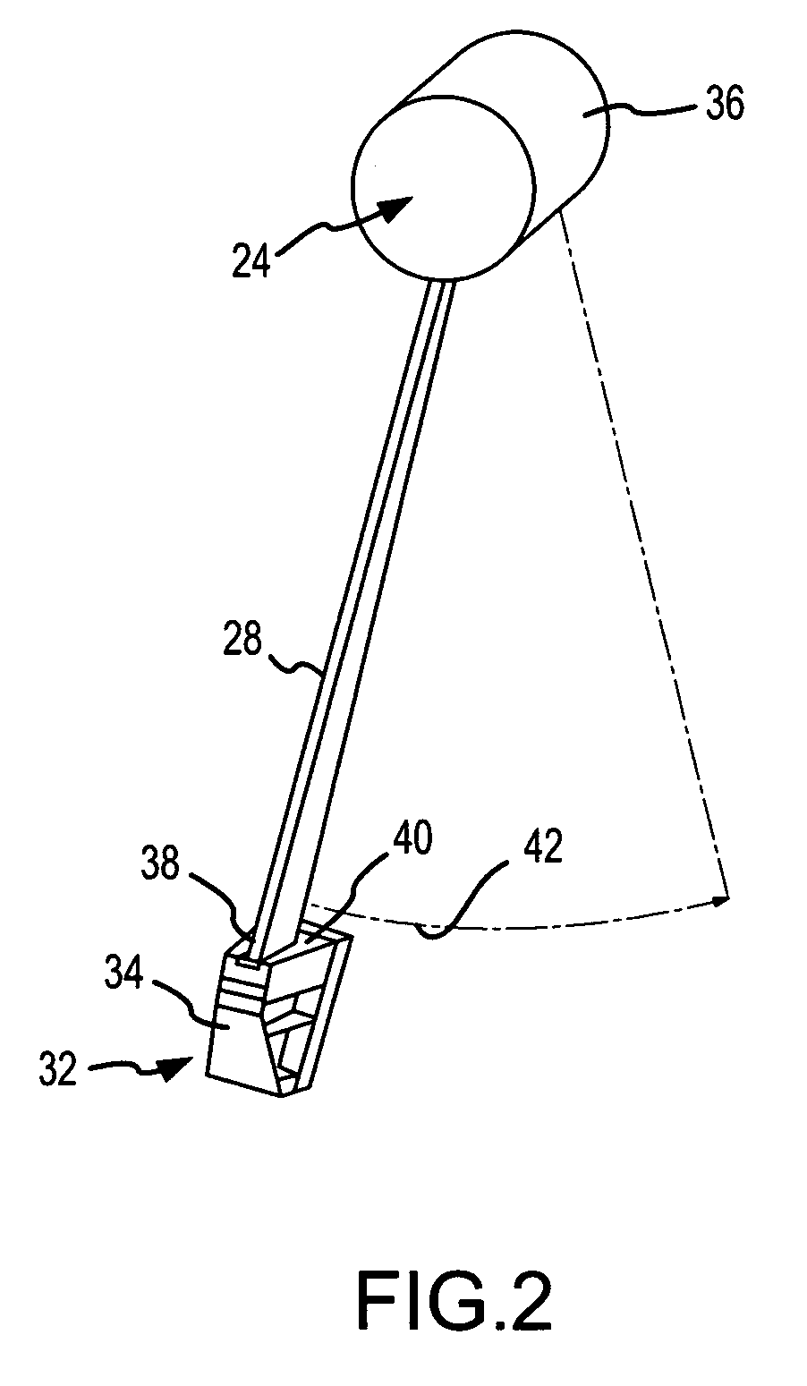
Scatter effects are reduced in a radiographic imaging device, such as a digital slot scan mammographic imaging device, by reducing detected scatter and processing detector information to compensate for scatter effects. A digital mammographic imaging system (10) may include a source (24) for transmitting a narrow beam (28) and a detector assembly (32) for detecting the beam (28). The beam (28) and the detector assembly (32) may synchronously scann across the patient's breast (48) to obtain an image. Collimator slats (74) at the leading and trailing edges of the detector may reduce detected scatter. Attenuators (76 and 92) at the ends of the scanned motion and at the anterior edge of the detector array may assist in determining a spatial intensity profile. The spatial intensity profile information together with other imaging signal and patient dependent parameters may be used to estimate and compensate for various scatter effects.

Description

FIELD OF THE INVENTION[0001]The present invention generally relates to medical imaging systems, and more particularly, to a method and system for enhancing radiographic images by removing or otherwise reducing the effects of scatter.BACKGROUND OF THE INVENTION[0002]Medical imaging is considered to be one of the most demanding applications of radiographic imaging, at least in terms of resolution and / or contrast. For instance, in the case of mammography it is generally desirable that a given imaging system be capable of obtaining images with a resolution on the order of fifty microns or better. Contrast requirements are also quite demanding since potential lesions and / or suspicious masses may exhibit x-ray attenuation characteristics similar to that of surrounding “healthy” tissue. With early detection of these lesions and / or masses being extremely desirable, enhancement of image resolution and / or contrast continues to be of increasing importance.[0003]Mammography has been performed u...

Claims


Application Information

Patent Timeline
Patent Type & Authority Patents(United States)
IPC IPC(8): A61B6/04A61B6/00A61B6/06
CPCA61B6/06A61B6/502A61B6/544A61B6/4291A61B6/0414
Inventor BESSON, GUY M.NIELDS, MORGAN W.TESIC, MIKE
Owner HOLOGIC INC
Learn More