Scanning transmission ion microscope

a transmission ion microscope and scanning technology, applied in the field of scanning transmission ion microscopes, can solve the problems of large, complex, and difficult to achieve the same resolution as tem, and achieve the effect of simple stem and easy operation

Active Publication Date: 2008-01-22
ALIS CORP
View PDF49 Cites 39 Cited by
  • Summary
  • Abstract
  • Description
  • Claims
  • Application Information

AI Technical Summary

Problems solved by technology

A TEM is a large, complex, expensive tool utilizing very high energy electrons.
The use of very high energy electrons is an operational burden.
STEM is somewhat simpler but cannot yield the same resolution as TEM.
These are slow methods that require mechanically scanning a very fine needle-shaped tip over the sample.
These methods cannot provide information on what is below the top atomic layer of the sample, however.

Method used


Image

  • Scanning transmission ion microscope
  • Scanning transmission ion microscope

Examples


Embodiment Construction

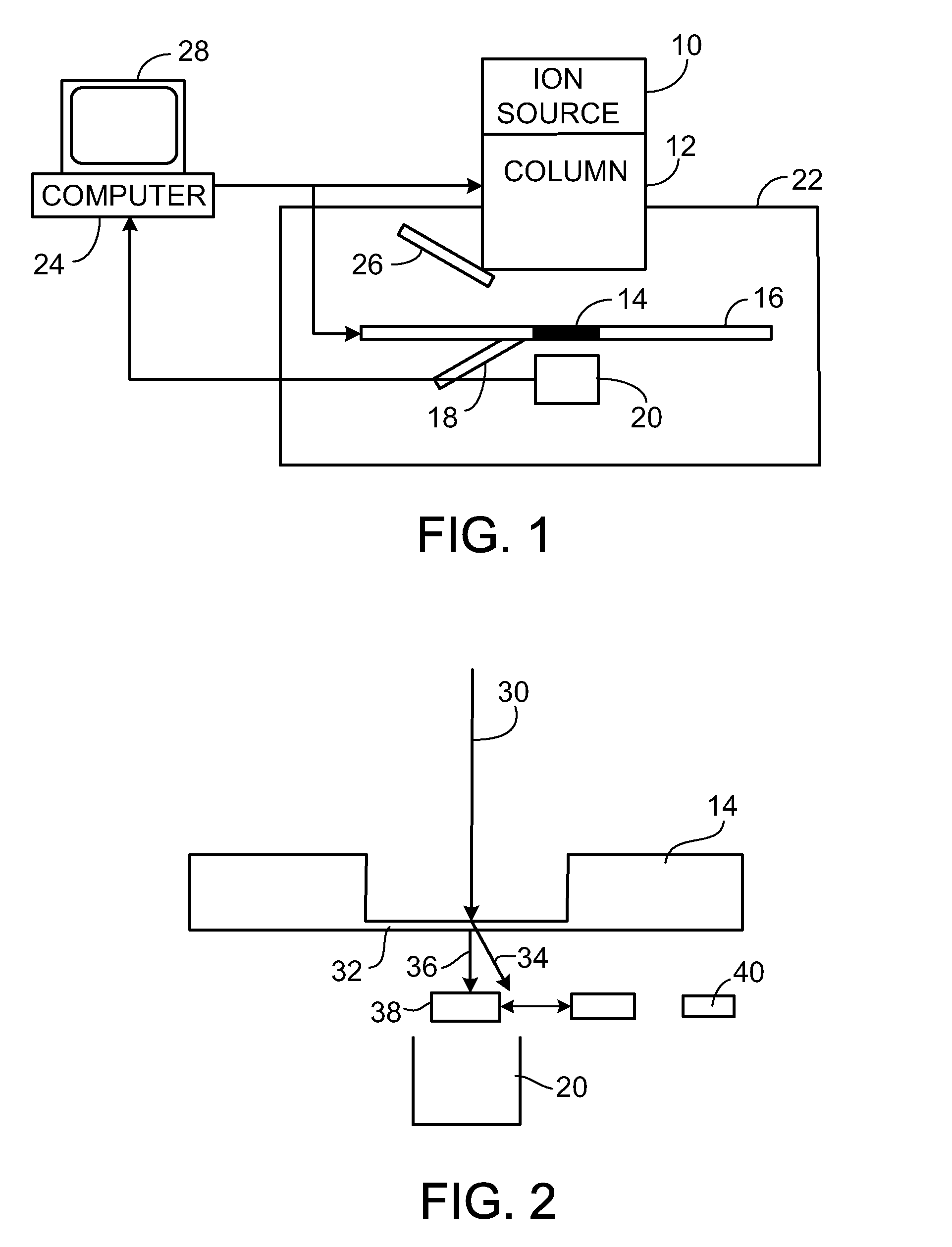
[0013]With reference first to FIG. 1, an ultra bright helium ion source 10 sends a beam of helium ions down focusing electrostatic column 12. The ions impinge upon a sample 14. The sample 14 is mounted on a translation stage 16. The sample holder 16 may be equipped with a cold finger 18 to allow variation of sample 14 temperature.

[0014]Ions transmitted through the sample 14 are detected by a detector 20. A vacuum enclosure 22 surrounds the sample 14 and the detector 20 as shown. A computer 24 provides fine placement of the ion beam on the sample 14 by providing deflection voltages that may or may not be amplified along with optical control voltages that are amplified by high voltage supplies (not shown) allowing control of beam focus and deflection. A low energy charge neutralizing electron beam unit 26 provides the ability to keep charge from building up on an electrically insulating sample.

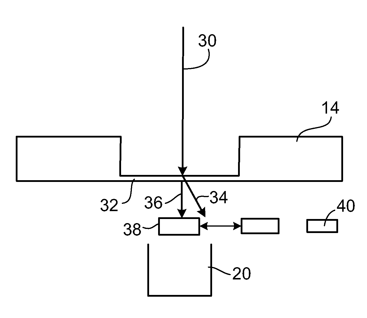
[0015]With the ion beam focused to sub-nanometer size, it is rastered over the sample that h...


PUM


Abstract

Scanning Transmission Ion Microscope. The microscope includes a bright helium ion source to generate an ion beam and a focusing electrostatic optical column to focus the ion beam. A translation stage supports a sample to receive the focused ion beam and a detector responds to ions transmitted through the sample to generate a signal from which properties of the sample may be displayed.

Description

BACKGROUND OF THE INVENTION[0001]This invention relates to ion microscopy and more particularly to a scanning transmission ion microscope.[0002]The structure of thin samples can currently be analyzed by scanning transmission electron microscopes (STEM) or by transmission electron microscopes (TEM). Both of these instruments detect changes in the primary electron beam when it interacts with the electronic structure of a sample. The focused probe used in STEM will, upon exit from the sample, provide information about the atomic spacing in the material and the atomic species through interactions that are sensitive to the atomic number Z at the beam position. TEM illuminates the sample all at once with a uniform electron beam so that the structure of the sample being examined imparts spatial information onto the beam. By looking at either the bright field (electrons which are transmitted) or dark field (electrons that are scattered), different types of sample information can be extracte...

Claims


Application Information

Patent Timeline
Patent Type & Authority Patents(United States)
IPC IPC(8): H01J37/30
CPCG01N23/04G01N23/225H01J37/08H01J37/28H01J2237/08H01J2237/0807H01J2237/2802
Inventor WARD, BILLY W.
Owner ALIS CORP
Why Eureka
Try Eureka