Method and program for converting boundary data into cell inner shape data

a cell inner shape and data technology, applied in the field of method and program for converting boundary data into cell inner shape data, can solve the problems of increasing the risk in the middle of development, the need for a lot of analysis time, and the need for many trials and errors

Inactive Publication Date: 2008-01-22
RIKEN
View PDF62 Cites 8 Cited by
  • Summary
  • Abstract
  • Description
  • Claims
  • Application Information

AI Technical Summary

Benefits of technology

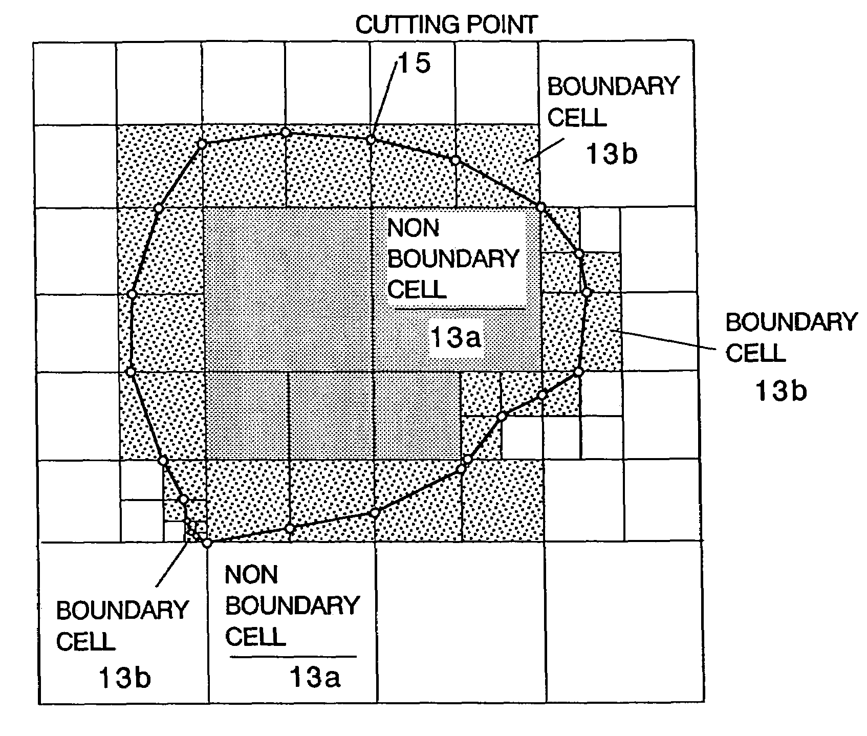
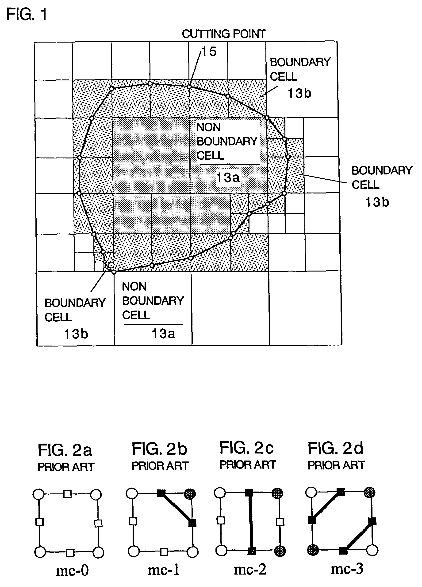
[0038]Additionally, in the boundary cell data classification step (E), the cell data constituting the boundary cell are classified into the internal cell data inside the cell inner shape data and the external cell data outside the cell inner shape data. Thus, it is possible to classify all the cell data into nonboundary and boundary cell data while maintaining continuity from adjacent cells.

Problems solved by technology

In a field of advanced research and development / technical developments, a higher level / complexity thereof has made a great many trials and errors absolutely necessary, increasing risks in the middle of developments.
Consequently, if data is heavy and simulation means (software or the like) is mounted, enormous data must be processed, causing a problem of much time necessary for analysis even when a large scale computer is used.
Thus, while data is light and an amount of data is small, there is not direct information regarding the inside of a boundary surface, causing a problem of unsuitability to deformation analysis or the like if no change is made.
However, unification of CAD and simulation is difficult, causing a problem of impossibility of managing the processes of designing, analyzing, fabricating, assembling, testing and the like based on the same data.
In other words, the following problems are inherent in the current solid / surface-CAD (referred to as S-CAD hereinafter):(1) data is not passed, inferior in internal conversion operation (problems of numerical value error and processing method);(2) direct use is impossible for simulation (mesh must be formed); and(3) investigation of fabrication by CAM is impossible (only last shape is given).
Additionally, the following problems are inherent in fabrication:(1) a fabrication process cannot be represented (rough fabrication or process design assistance is insufficient);(2) dealing with a new fabrication method such as laser fabrication or superadvanced fabrication is impossible (only cutting is available, numerical value accuracy is insufficient); and(3) a fabrication method itself cannot be selected (different material characteristics are given in compound material).
Therefore, it can be said that there are almost no fabrication technologies capable of truly utilizing volume data except laser stereolithography and rapid prototyping (3D ink jet).
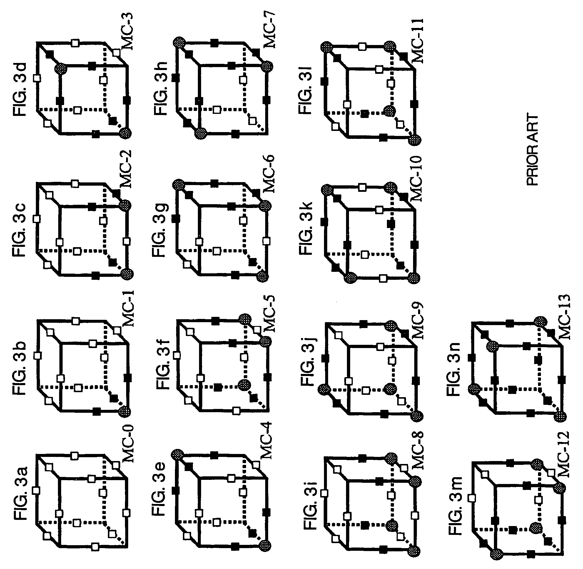
This means that current resolution is too rough to represent the shape from the standpoint of the MC.
Such defects frequently occur at an intersection of a curved boundary surface and a cell edge.
Furthermore, prevention of an increase in the storage capacity causes a difficulty of precisely representing a shape of a boundary part.

Method used


Image

  • Method and program for converting boundary data into cell inner shape data
  • Method and program for converting boundary data into cell inner shape data
  • Method and program for converting boundary data into cell inner shape data

Examples


Embodiment Construction

[0072]Next, the preferred embodiments of the present invention will be described with reference to the accompanying drawings.

[0073]FIG. 6 is a flowchart of a method and a program for converting data according to the present invention. As shown, each of the method and the program of the invention comprises a division step (A), a cutting point deciding step (B), a boundary deciding step (C), a cell classification step (D), and a boundary cell data classification step (E).

[0074]External data 12 input from the outside is polygon data indicating a polyhedron, a tetrahedron or hexahedron element used for a finite element method, curved surface data used for three-dimensional CAD or a CG tool, or data in which the other solid surface is represented by information containing a partial plane or curved surface.

[0075]In addition to such data (referred to as S-CAD data), the external data 12 may be (1) data directly prepared by a human input through a boundary surface of V-CAD's own (V-boundary...


PUM


Abstract

A method and a program for converting boundary data into cell inner shape data, includes a division step (A) of dividing external data (12) constituted of the boundary data of an object into cells (13) in an orthogonal grid, a cutting point deciding step (B) of deciding an intersection point of the boundary data and a cell edge as a cell edge cutting point, a boundary deciding step (C) of deciding a boundary formed by connecting the cell edge cutting points as the cell inner shape data, a cell classification step (D) of classifying the divided cells into a nonboundary cell (13a) including no boundary surface and a boundary cell (13b) including a boundary surface, and a boundary cell data classification step (E) of classifying cell data constituting the boundary cell into internal cell data inside the cell inner shape data and external cell data outside the cell inner shape data.

Description

[0001]This is a National Phase Application in the United States of International Patent Application No. PCT / JP03 / 02197 filed Feb. 27, 2003, which claims priority on Japanese Patent Application No. 053575 / 2002, filed Feb. 28, 2002. The entire disclosures of the above patent applications are hereby incorporated by reference.BACKGROUND OF THE INVENTION[0002]1. Technical Field of the Invention[0003]The present invention relates to a method for storing substantial data which can unify CAD and simulation by storing the substantial data that integrates a shape and physical properties by a small storage capacity, and more particularly to a method and a program for converting boundary data into cell inner shape data.[0004]2. Description of the Related Art[0005]In a field of advanced research and development / technical developments, a higher level / complexity thereof has made a great many trials and errors absolutely necessary, increasing risks in the middle of developments. In Japan that depen...

Claims


Application Information

Patent Timeline
Patent Type & Authority Patents(United States)
IPC IPC(8): G06T17/00G06F17/50
CPCG06F17/5018G06T17/00B33Y50/00G06F30/23
Inventor TESHIMA, YOSHINORIKASE, KIWAMUUSAMI, SHUGOMAKINOUCHI, AKITAKE
Owner RIKEN
Why Eureka
Try Eureka