Method and optical arrangement for beam guiding of a light beam with beam delay

a technology of beam delay and beam guiding, which is applied in the direction of optical radiation measurement, instruments, photomechanical equipment, etc., can solve the problems of shortening the service life, affecting the efficiency of optical elements, so as to achieve the effect of reducing the number of optical elements

Active Publication Date: 2008-01-22
CARL ZEISS SMT GMBH
View PDF11 Cites 34 Cited by
  • Summary
  • Abstract
  • Description
  • Claims
  • Application Information

AI Technical Summary

Benefits of technology

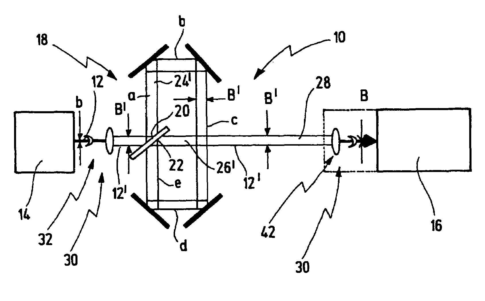
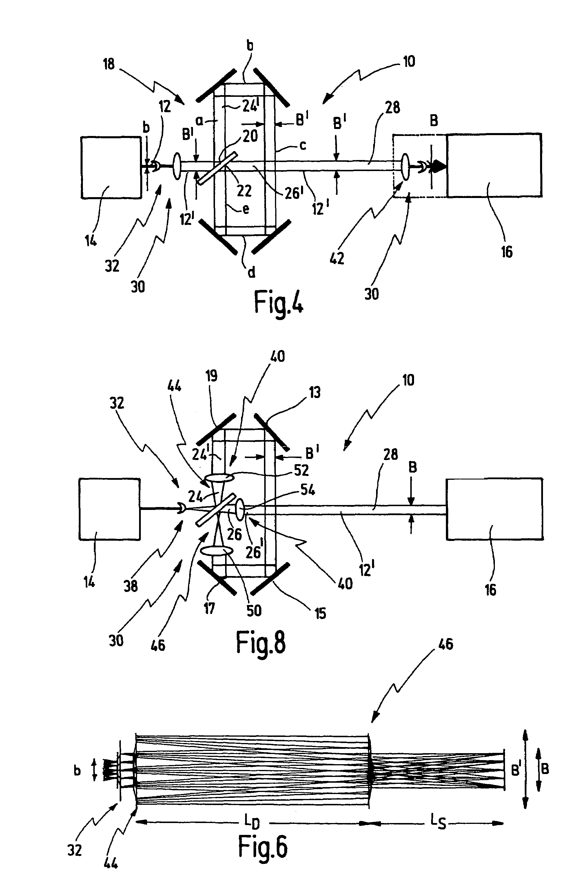
[0018]The invention is based on the insight that it is possible to achieve significantly larger transmission distances for the light beam and thus significantly larger delay path distances LD if the light beam is expanded in the meantime to a beam width B′ that is greater than the beam width B at the target location, since it has been recognized that the maximum transmission path from the light source to the target location on which the beam propagates with homogeneous intensity distribution is proportional to the square of the expansion of the light beam. If, as in the case of conventional beam guiding systems, the light beam coming from the light source were shaped or expanded only to the predetermined desired beam width B that is intended to prevail at the target location, the maximum transmission paths are limited to path distances that are insufficient, under certain circumstances, for sufficient pulse elongation or multiplication. The methods according to the invention and the optical arrangement according to the invention therefore make it possible to obtain transmission lengths that are significantly greater than in the case of conventional systems, in which case, over these greater transmission lengths, there is no significant change in the beam width over the entire delay length and the entire beam guiding length except for the interim greater beam expansion, without this requiring, within the delay line, imaging optics that image the input of the delay line onto the output thereof.
[0023]In this case, as in the previous case, it is advantageously possible to work with two expansion optics, which has the advantage that the overall focal length of the expansion optic in the delay line and the expansion optic in the direct beam guiding along the path distance LS can be adjusted independently of one another by slightly displacing the positive lenses of the expansion optics and it is thus possible to compensate for slight refractive powers of the mirrors that are caused, if appropriate, by tolerances of the deflection mirrors in the delay line.
[0047]It is equally preferred for at least one prism to be used for the at least one expansion optic, since said prism may simultaneously also be used as a beam splitter at the input and / or as a beam combining element at the output of the delay line, as a result of which the number of optical elements can advantageously be reduced.
[0048]Furthermore, the beam guiding optic may preferably have at least one optical element with variable refractive power, which enable adjustment of the focal length f of the beam guiding optic or of the at least one expansion optic, and / or compensation of undesirable refractive powers caused, by way of example, by tolerances or deformations of the folding mirrors used in the delay line, and / or adaptation of the beam guiding to different path distances LS and / or LD. A variable adaptation of the optical arrangement according to the invention to different purposes of use can be made possible in this way.

Problems solved by technology

These high power densities can damage the downstream optical systems or shorten the service life thereof.
In this case, the problem exists that the light beam generated by the light source naturally has a beam divergence, i.e. becomes wider and wider as the path distance increases.
The use of the abovementioned delay lines having an imaging optic that images the input of the delay line onto the output of the delay line has the disadvantage, however, that additional focusing elements are required in the delay line, which constitute an additional cost expenditure.
Furthermore, these imaging optics within the delay line generate intermediate foci which constitute a high radiation burden per volume and accordingly have to be well purged or arranged remote from optical elements.
Moreover, the optical elements, for example folding mirrors, present in the delay line are burdened to a greater extent by the focusing.
If, by contrast, imaging within the delay line is dispensed with, the disadvantage already mentioned arises in that the delayed partial beam, due to the natural divergence of the laser radiation and due to the longer propagation path via the delay line, no longer falls within the specified beam width range, but rather is increasingly fanned out over the propagation path, with the result that the predetermined beam width B desired at the target location is exceeded.

Method used


Image

  • Method and optical arrangement for beam guiding of a light beam with beam delay
  • Method and optical arrangement for beam guiding of a light beam with beam delay
  • Method and optical arrangement for beam guiding of a light beam with beam delay

Examples


Embodiment Construction

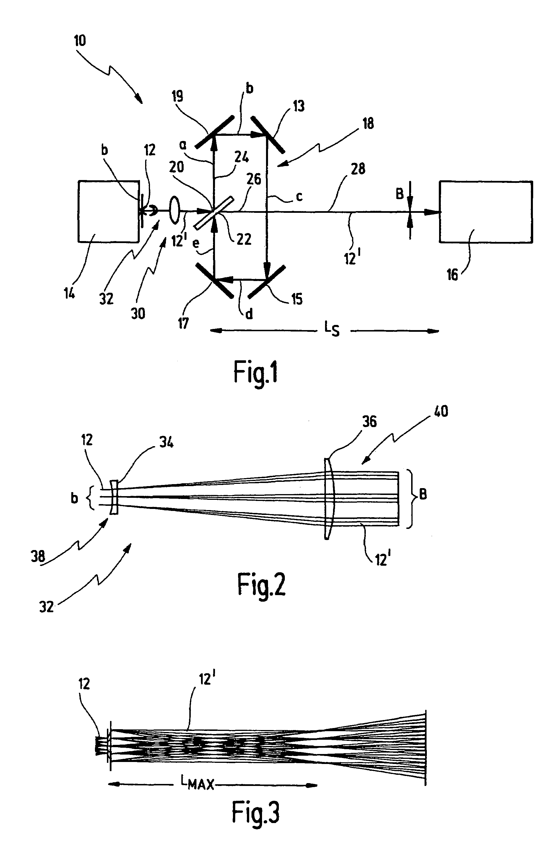
[0061]Firstly, the principle of an optical arrangement for beam guiding of a light beam from a light source to a target location is described with reference to FIGS. 1 to 3. The basic relationships of the beam guiding are elucidated in this case.

[0062]FIG. 1 illustrates an optical arrangement—provided with the general reference symbol 10—for beam guiding of a light beam 12 generated by a light source 14. The optical arrangement 10 has the function of guiding the light beam 12 to a target location 16, and if appropriate shaping said light beam.

[0063]In the case of the preferred use of the optical arrangement 10, the light source 14 is a laser, for example an excimer laser, which generates pulsed laser light, with the result that the light beam 12 is constructed from individual light pulses. In this application, the target location 16 is a projection individual light pulses. In this application, the target location 16 is a projection exposure installation, by way of example, by means ...


PUM

PropertyMeasurementUnit
pulse energyaaaaaaaaaa
transmission path distance LMAXaaaaaaaaaa
path distances LSaaaaaaaaaa

Abstract

A method for beam guiding of a light beam generated by a light source to a target location along a path distance LS, comprises splitting the light beam on the path distance LS at least once into a first partial beam and a second partial beam, guiding the first partial beam additionally at least once along a delay line, the first partial beam thereby covering an additional path distance LD, guiding the second partial beam only along the path distance LS, combining the first and second partial beams after the first partial beam having passed through the delay line and guiding the combined beam to the target location, wherein the light beam is guided along the path distance LS and LD in such a way that the light beam generated by the light source has a predetermined beam width B at the target location, expanding the light beam between the light source and the target location at least once to a beam width B′>B and comprising the light beam again at least once in such a way that the light beam has the predetermined beam width B at the target location.

Description

PRIOR APPLICATION[0001]Applicants claim priority benefits under 35 U.S.C. §119(e) of U.S. Provisional Patent Application Ser. No. 60 / 529,604 filed Dec. 15, 2003.BACKGROUND OF THE INVENTION[0002]The invention relates to a method for beam guiding of a light beam generated by a light source, in particular laser light source, to a target location along a path distance LS.[0003]The invention furthermore relates to an optical arrangement for beam guiding of a light beam generated by a light source, in particular laser light source, to a target location along a path distance LS.[0004]A specific application described in connection with the present invention is the use of the method mentioned in the introduction and of the optical arrangement mentioned in the introduction in semiconductor lithography.[0005]In semiconductor lithography, laser light is used to image a mask onto a wafer by means of a projection exposure installation in order then to fabricate the desired semiconductor component...

Claims


Application Information

Patent Timeline
Patent Type & Authority Patents(United States)
IPC IPC(8): G02B27/10G02B27/12G02B5/08H01S3/08H01S3/081G02B27/14G03F7/20
CPCG02B27/126G02B27/144G02B27/145G03F7/70041G03F7/7055
Inventor HERKOMMER, ALOISMUENZ, HOLGERSEIFERT, WOLFGANG
Owner CARL ZEISS SMT GMBH
Why Eureka
Try Eureka