Cortical and cancellous allograft cervical fusion block

a cervical fusion block and allograft technology, applied in the field of surgical implants, can solve the problems of abnormal force applied to the cervical vertebra, bone material erosion, bone material erosion, etc., and achieve the effects of accelerating the healing process, ensuring the overall strength and durability of the structure, and effectively promoting new bone growth

Inactive Publication Date: 2008-01-29
MUSCULOSKELETAL TRANSPLANT FOUND INC
View PDF19 Cites 165 Cited by
  • Summary
  • Abstract
  • Description
  • Claims
  • Application Information

AI Technical Summary

Benefits of technology

[0024]It is another object of the invention to utilize a shaped cortical cancellous bone implant block which provides the mechanical strength characteristics that can withstand compression forces and provide overall strength and durability to the structure.
[0025]It is still another object of the invention to provide a spinal fusion implant which uses a load bearing component member to take up the high forces which can arise between two vertebral bodies and a relatively porous cancellous component member to accelerate the healing process.
[0026]It is yet another object of the invention to provide a pre-machined shaped allograft bone structure which can effectively promote new bone growth and accelerate healing.
[0027]It is also an object of the invention to create a sterile bone fusion implant, which is sterile and which can be easily handled by the physician during surgery which eliminates or significantly reduces the physician from having to carve or modify the respective bone blocks.

Problems solved by technology

Injury or disease processes to the head, neck, or shoulders can cause abnormal forces to be applied on the cervical vertebra.
Metal plates screwed into the adjacent vertebrae work well, but after some time post-operatively, the stress rise occurring at the screw position causes erosion of the bone and resultant slipping.
However, bone material and in particular cortical bone acceptable for use in implants is a scarce resource, being derived from limited number human tissue donor resources.
However, these long bones make up only a fraction of the available bone source.
However, the lower mechanical strength of cancellous bone prohibits its use in many surgical applications.
Thus, sources of bone suitable for structural intervertebral spacers are extremely limited.
The scarcity of desired donor bone makes it difficult to provide implants having the desired size and configuration for implantation between vertebrae, which can require relatively large implants.
The scarcity of suitable bone material has also hindered efforts to design and manufacture varying configurations of suitable implants for arthodesis of the spine.
Further, various implant configurations have not been physiologically possible to obtain given the structural and geometrical constraints of available donor bone.

Method used


Image

  • Cortical and cancellous allograft cervical fusion block
  • Cortical and cancellous allograft cervical fusion block
  • Cortical and cancellous allograft cervical fusion block

Examples


Embodiment Construction

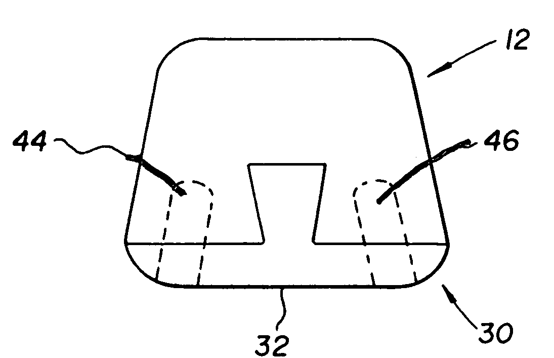
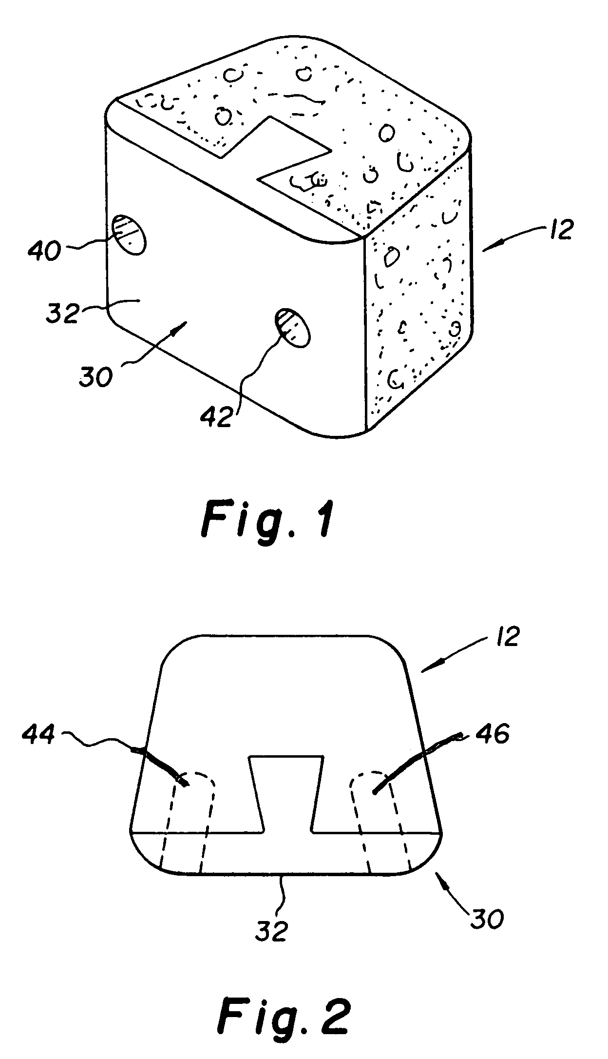
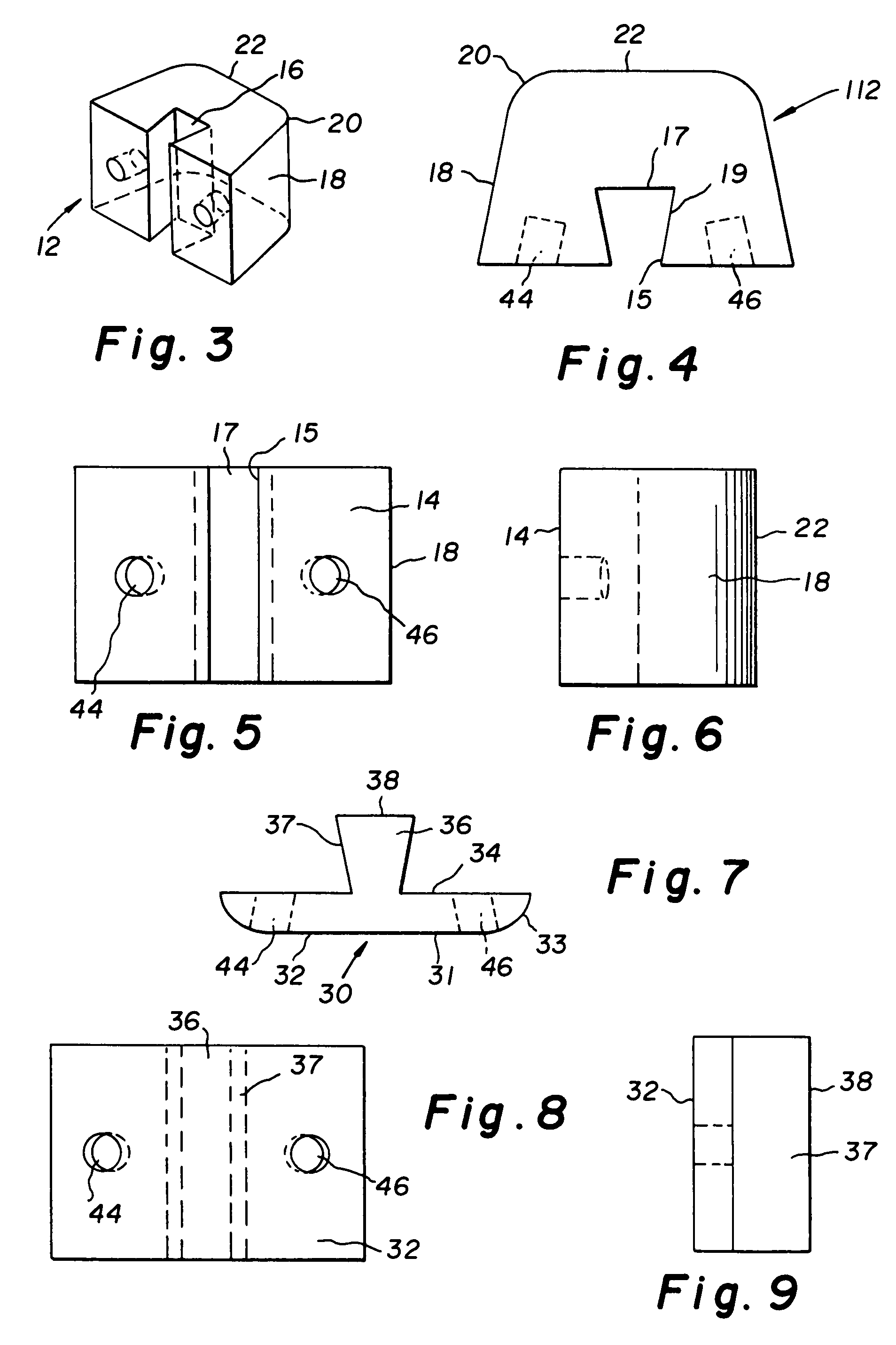
[0058]The preferred embodiment and best mode of the present invention is shown in FIGS. 1 through 9. The composite bone implant block 10 is shown in FIG. 1 in accordance with the present invention.

[0059]The composite cortical cancellous bone block body or intervertebral spacer 10 is preferably constructed with a first component member 12 of denser cancellous bone taken from donors age 45 or less cut into a truncated triangle shape. This component accounts for a large portion of the graft and provides a large area for bone fusion to occur. The component member body has a flat planar front end surface 14 and is provided with a dove tail shaped recess 16 cut therein into the interior of the cancellous component body. The dove tail shaped recess 16 extends from the access port or opening 15 to the base wall 17 forming the rear of the recess. The access entrance opening 15 is preferably about twice as wide as the base 17 of the recess and the side walls 19 of the recess are angled from 7...


PUM


Abstract

A sterile composite bone graft for use in implants comprising a T shaped cortical bone load bearing member mated to a cancellous member. The crosspiece of the T defines an inner planar surface and dove tail shaped mating member extends outward from the inner planar surface. The allograft cancellous bone member defines tapered side walls on the exterior surface of the body, a flat proximal end surface and a flat distal end surface. A dove tail shaped recess with the narrowest portion exiting the flat proximal end surface is cut into the interior of the cancellous member body. The dove tail shaped member and dove tail shaped recess are mated together to hold both component members together. Pins are mounted in both members to provide additional stability.

Description

RELATED APPLICATION[0001]There are no related applications.FIELD OF INVENTION[0002]The present invention is generally directed toward a surgical implant product and more specifically is a shaped allograft cortical cancellous bone block implant for the fusion of vertebral bones which is introduced between two vertebral bones to be fused.BACKGROUND OF THE INVENTION[0003]The use of substitute bone tissue dates back around 1800. Since that time research efforts have been undertaken toward the use of materials which are close to bone in composition to facilitate integration of bone grafts. Developments have taken place in the use of grafts to use materials such as corals, hydroxyapatites, ceramics or synthetic materials such as biodegradable polymer materials. Surgical implants should be designed to be biocompatible in order to successfully perform their intended function. Biocompatibility may be defined as the characteristic of an implant acting in such a way as to allow its therapeutic...

Claims


Application Information

Patent Timeline
Patent Type & Authority Patents(United States)
IPC IPC(8): A61F2/44A61F2/00A61F2/28A61F2/30A61F2/46
CPCA61F2/447A61F2/28A61F2310/00359A61F2002/2817A61F2002/30006A61F2002/30011A61F2002/30013A61F2002/30057A61F2002/30387A61F2002/30492A61F2002/30677A61F2002/4649A61F2220/0025A61F2250/0015A61F2250/0018A61F2250/0023A61F2250/0024
Inventor SHEPARD, YOLANDA DENISEOLIVOS SANCHEZ, MANUEL A.
Owner MUSCULOSKELETAL TRANSPLANT FOUND INC
Why Eureka
Try Eureka