Cooling system for computer

a cooling system and computer technology, applied in the field of cooling systems, can solve the problems of shortening the useful life of the components, reducing the performance of the components of the system, and deteriorating the performance of the electronic components, so as to facilitate the absorption of heat and facilitate the dissipation of hea

Inactive Publication Date: 2008-02-05
HON HAI PRECISION IND CO LTD +1
View PDF18 Cites 11 Cited by
  • Summary
  • Abstract
  • Description
  • Claims
  • Application Information

AI Technical Summary

Benefits of technology

[0015]According to an embodiment of the present invention, a computer system is closed from surrounding atmosphere so that dust in the surrounding atmosphere cannot enter the computer system to contaminate electronic components therein. The computer system includes a cooling system consisting of a housing for hermetically coupled to a computer case of the computer system. The housing comprises a lateral wall having a lower protrusion and an upper protrusion. A thermoelectric module is received in the housing and has a cold side and a hot side when subject to an electric voltage. The computer case comprises a CPU therein and a side panel having a lower opening and an upper opening. A first fan mounted to the upper opening is connected with the upper protrusion for blowing hot air generated by the CPU to the cold side of the thermoelectric module. A second fan mounted to the lower opening is connected with the lower protrusion for blowing cold air from the cold side of the thermoelectric module to the CPU. A first heat sink is mounted to the cold side of the thermoelectric module for facilitating absorption of heat from the hot air to the cold side of the thermoelectric module. A second heat sink is mounted to the hot side of the thermoelectric module for facilitating dissipation of the heat from the hot side of the thermoelectric module to the surrounding atmosphere.

Problems solved by technology

High temperature can reduce the performance of the components of the system and even shorten the useful life of the components.
The accumulated fibrous materials and conductive particles can increase electrical resistance of the wires, or shorten the wires, whereby the performance of the electronic components deteriorates, or even the electronic components break down.

Method used


Image

  • Cooling system for computer
  • Cooling system for computer
  • Cooling system for computer

Examples


Embodiment Construction

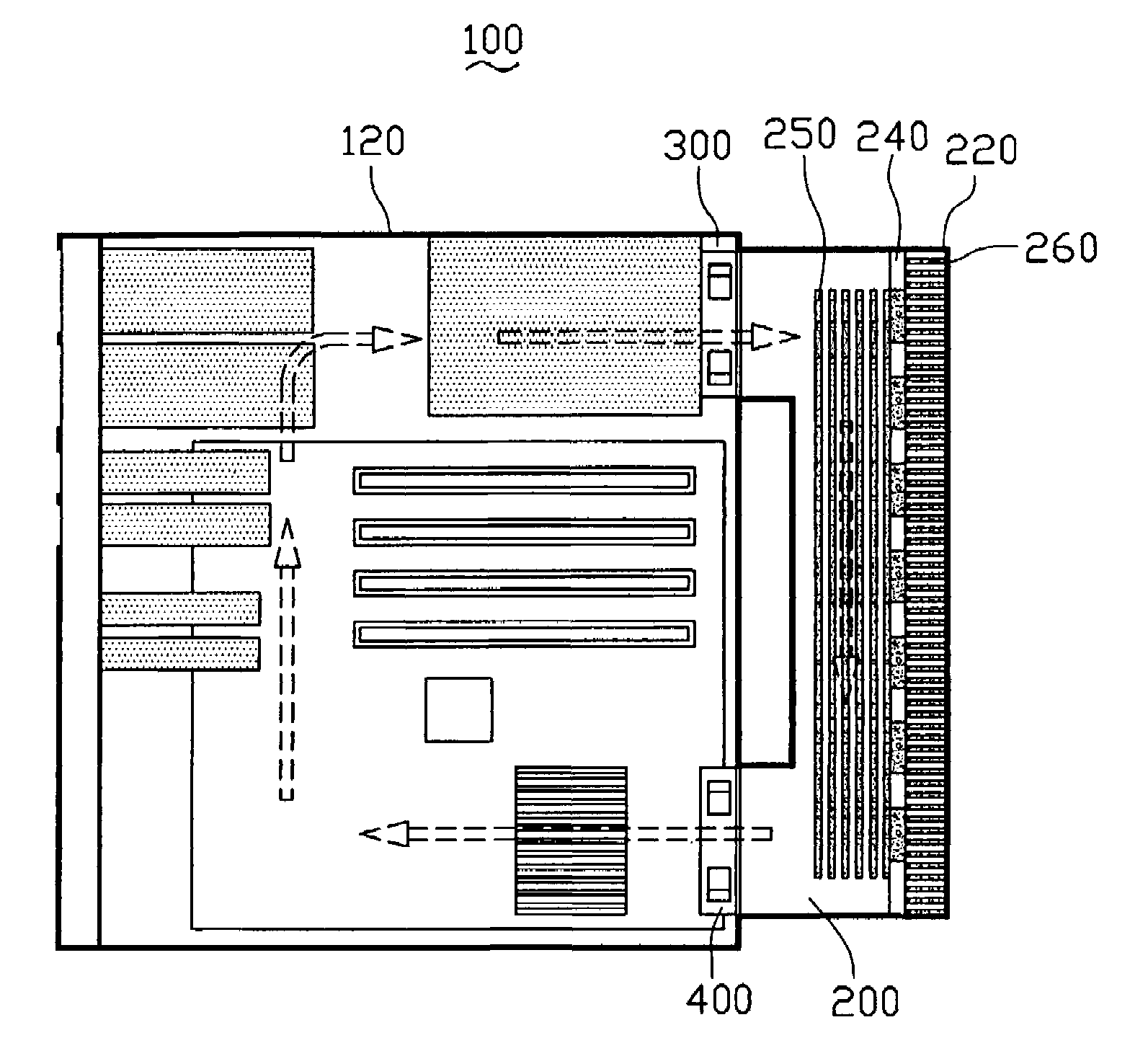
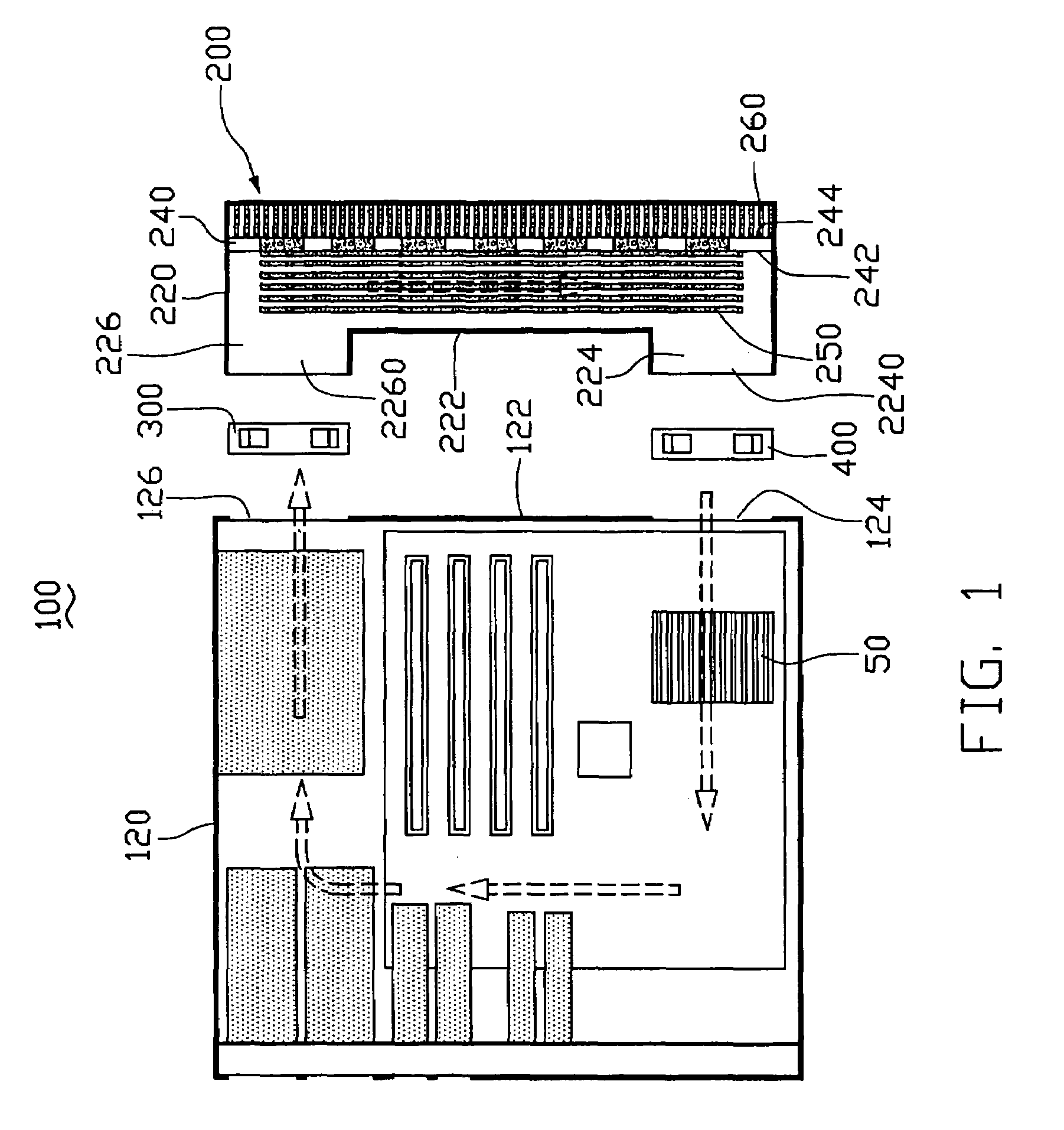
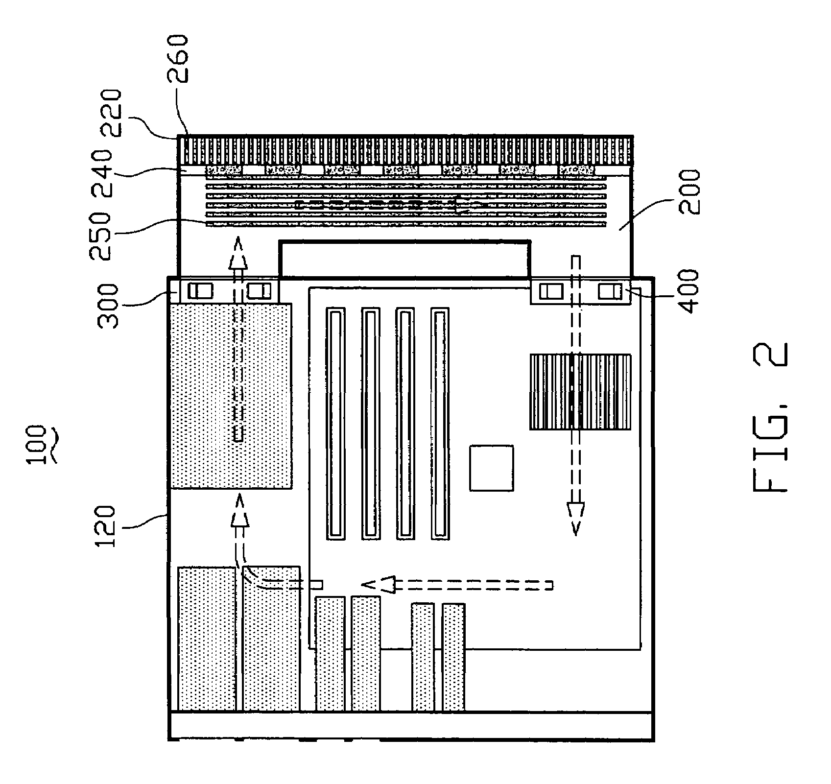
[0023]FIG. 1 shows a computer system 100 comprising a casing 120 in which a heat generating component, CPU 50 is disposed, and a cooling system 200. The casing 120 comprises a side panel 122. The side panel 122 defines a lower opening 124 and an upper opening 126 respectively at bottom and top ends thereof. A first fan 300 and a second fan 400 are respectively received in the upper and lower openings 126, 124. The cooling system 200 comprises a housing 220, a thermoelectric module 240, a first heat sink 250 and a second heat sink 260. The housing 220 comprises a lower protrusion 224 corresponding to the lower opening 124 of the casing 120 and an upper protrusion 226 corresponding to the upper opening 126 of the casing 120. The housing 220 further comprises a lateral wall 222 connecting the lower protrusion 224 and the upper protrusion 226. The lateral wall 222 is located facing the side panel 122 of the casing 120. The lower protrusion 224 and the upper protrusion 226 respectively h...


PUM


Abstract

A cooling system (200) for a computer system (100) includes a housing (220) and a thermoelectric module (240) in the housing. The housing is hermetically connected to a computer case (120). The thermoelectric module comprises a cold side (242) and a hot side (244) when subject to an electric voltage. A first fan (300) is for blowing hot air generated by a CPU (50) in the computer case to the cold side of the thermoelectric module. A second fan (400) is for blowing cold air from the cold side of the thermoelectric module to the CPU. A first heat sink (250) is mounted to the cold side of the thermoelectric module. A second heat sink (260) is mounted to the hot side of the thermoelectric module.

Description

BACKGROUND[0001]1. Field[0002]The present invention relates to a cooling system, and particularly to a cooling system for a hermetical computer system having a thermoelectric chip therein, wherein heat generated by heat-generating components in the computer system is cooled by the thermoelectric chip.[0003]2. Prior Art[0004]As is widely known, a computer system, generally has heat sources such as CPU, MOS, a power supply or other computer components. The heat sources generate heat which, if not dealt with, increases the temperature in the computer system. High temperature can reduce the performance of the components of the system and even shorten the useful life of the components.[0005]Thus, a cooling system is often provided to the computer system to remove the heat generated by the heat sources.[0006]In this respect, conventional computer systems are cooled by either positive pressure cooling technology or negative pressure cooling technology. The positive pressure cooling technol...

Claims


Application Information

Patent Timeline
Patent Type & Authority Patents(United States)
IPC IPC(8): F25B21/02F25D23/12F28D15/00H05K7/20
CPCG06F1/20
Inventor LEE, TSUNG-LUNGLIU, ZHI-GANG
Owner HON HAI PRECISION IND CO LTD
Why Eureka
Try Eureka