Welding material and a method of producing welded joint

a technology of welded joints and welding materials, which is applied in the field of welding materials, can solve the problems of low alloy steel materials of such a type quite often experiencing cracking, low temperature cracking at welded joints of high strength steel materials, and generating cracks therein, so as to improve the fatigue strength of the welded joint and prevent the effect of low temperature cracking

Inactive Publication Date: 2008-02-05
NAT INST FOR MATERIALS SCI
View PDF15 Cites 8 Cited by
  • Summary
  • Abstract
  • Description
  • Claims
  • Application Information

AI Technical Summary

Benefits of technology

[0017]An object of the present invention is to solve the aforementioned problems of the prior art and to propose a welding material and a method of producing a welded joint, in which low-temperature cracking of a welded joint of high-tensile strength on steel of 490-1180 MPa can be prevented without performing pre-heating, the fatigue strength of the welded joint can be enhanced, and the strength of the weld metal can be adjusted at an appropriate value. It is also an object of the present invention to propose a welded joint in which low temperature cracking during welding can be prevented.
[0019]As a result, the inventors of the present invention discovered that, in order to enhance the fatigue strength of the welded joint, it is very important that the weld metal has a composition exhibiting a temperature-elongation curve (a thermal expansion curve) in which the weld metal experiences martensitic transformation during the cooling process after the welding and the weld metal reaches, after being cooled to the room temperature, a state in which the weld metal is expanded as compared with the state thereof when the martensitic transformation started.
[0020]In addition, the inventors of the present invention discovered that, due to the weld metal experiencing the martensitic transformation during the cooling process after welding and reaching a state, at the room temperature, in which the weld metal is expanded as compared with the state thereof when the martensitic transformation started, the tensile residual stress generated in the weld metal during the cooling process can be alleviated or converted to a compressive residual stress. Further, the inventors discovered that, due to the same mechanism, the tensile stress is prevented from concentrating on the end portion or the root portion which is hardened by the welding heat, the fatigue strength of the welded joint portion is enhanced, and the diffusive hydrogen is prevented from diffusing and concentrating to the end portion or the root portion, thereby allowing preventing of the low-temperature cracking without pre-heating.
[0022]Yet further, the present inventors discovered that, by having an adequate amount of austenite remain in the weld metal, the strength of the weld metal can be adjusted so as to be in an appropriate range and too high a degree of over-matching (over-matching results from the strength of the weld metal being too high) can be prevented, while maintaining the aforementioned properties of the weld metal.

Problems solved by technology

However, a low alloy steel material of such a type quite often experiences occurrence of cracking at a low temperature during welding.
Such low-temperature cracking at welded joints of the high strength steel material is mainly caused by hydrogen which has been dissolved into the weld metal during the welding process.
During the cooling the hydrogen diffuses and concentrates especially on the stress-concentrating portions such as the stop-end portion and the root portion which have been hardened by the welding heat, thereby generating cracks therein.
It is well known that, the more such diffusive hydrogen is dissolved in the weld metal and the higher the stresses are, the more likely the low-temperature weld-cracking is to occur.
However, pre-heating and / or post-heating during welding is extremely painstaking and time-consuming work, which inevitably results in the higher cost for welding operation and lower efficiency of welding operation.
However, the technique disclosed in JP-A 9-253860 Laid-Open is limited to the TIG welding.
That is, there is a problem that, if other welding methods in which the amount of diffusive hydrogen is relatively large (2 wt. ppm or more) are employed in the technique, pre-heating will still be required in order to prevent weld-cracking.
In addition, in the technique described in JP-A 11-138290 Laid-Open, there arises what is called the “over-matching” problem in which the strength of the weld metal becomes larger than the strength of the welded materials.

Method used


Image

  • Welding material and a method of producing welded joint
  • Welding material and a method of producing welded joint
  • Welding material and a method of producing welded joint

Examples


example 1

[0090]The weld-cracking properties were investigated by: using the low alloy steel materials (steel plates) having the compositions shown in Table 1 as the material to be welded; using the compositions shown in Table 2 (the compositions of deposital metal measured according to JIS Z 3111) as the welding material; and using test pieces according to the regulations of JIS Z 3158, under the welding conditions shown in Table 3.

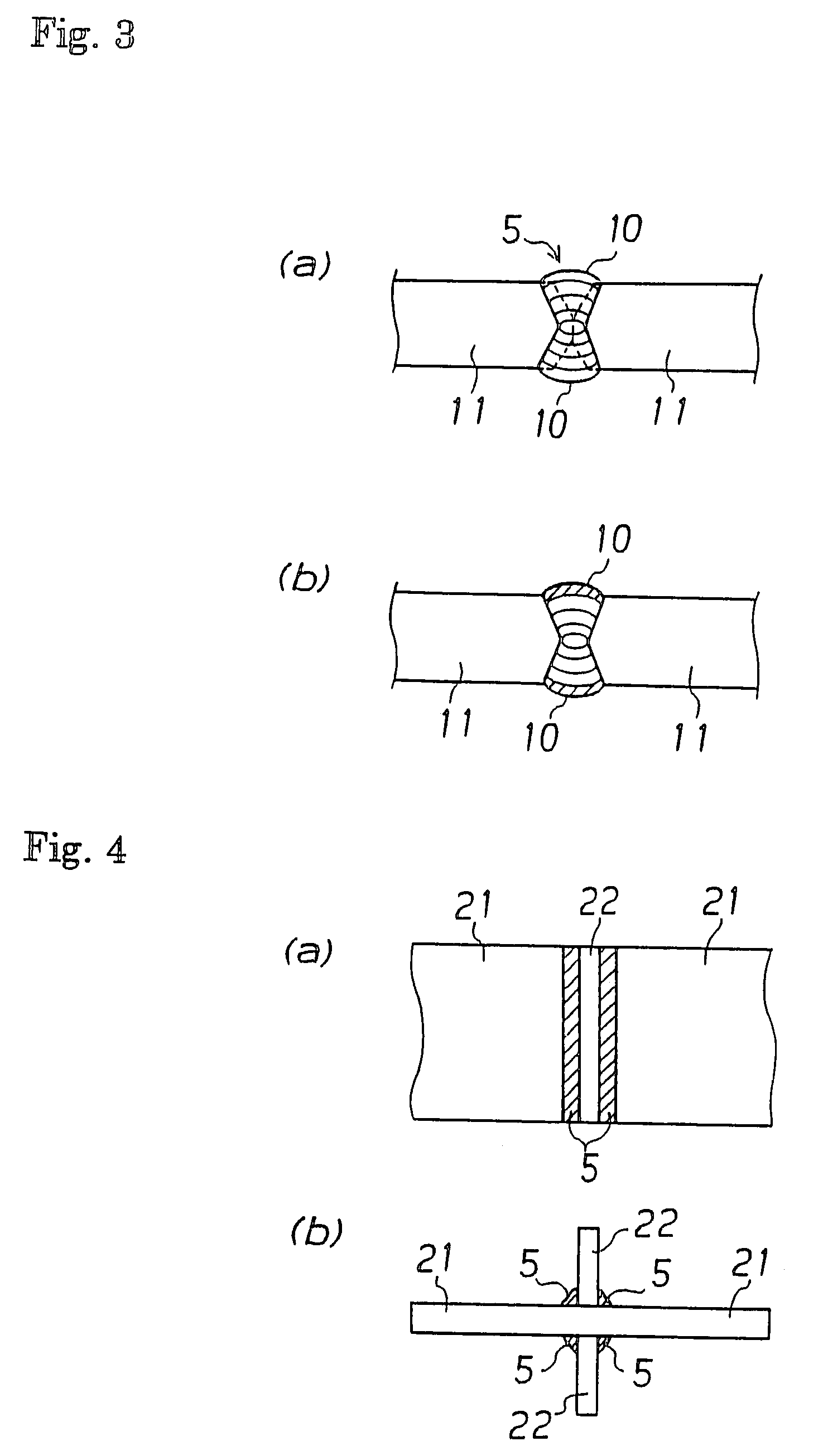
[0091]The tests were conducted in an atmosphere in which the temperature was 30° C. and the relative humidity was 80% as condition 1 and in an atmosphere in which the temperature was 20° C. and the relative humidity was 60% as condition 2, without pre-heating. The test-repeating number was 3, and with respect to the crack generated in the welded portion, presence / absence of crack and the crack rate were measured according to the regulations of JIS Z 3158. The results are shown in FIG. 4.

[0092]In the present example, no low-temperature-cracking was observed, althou...

example 2

[0093]A butt welded joint and a cruciform welded joint (the joint length was 0.5 m) shown in FIGS. 3 and 4 were produced by: using the low alloy steel materials (steel plates) having the compositions shown in Table 1 as the material to be welded; and using some of the welding materials whose compositions (the compositions of diposital metal measured according to JIS Z 3111) are shown in Table 2, under the welding conditions shown in Table 5 (without pre-heating and post-heating).

[0094]With respect to these welded joints, the state of crack-generation in the welded portions were investigated by observing the surface of the portions. In addition, with respect to each welded joint, the hardness of the parent material portion and the hardness of the weld metal portion (the average hardness of the weld metal section) were measured. Further, the amount of residual austenite in the weld metal was measured by the X-ray diffraction method. Yet further, fatigue test pieces were collected from...

example 3

[0096]The weld-cracking properties were investigated by: using the low alloy steel materials (steel plates) having the compositions shown in Table 7 as the material to be welded; using the compositions shown in Table 8 (the compositions of deposital metal measured according to JIS Z 3111) as the welding material; and using test pieces according to the regulations of JIS Z 3158, under the welding conditions shown in Table 9.

[0097]The tests were conducted in an atmosphere in which the temperature was 30° C. and the relative humidity was 80% (condition 1) and in an atmosphere in which the temperature was 20° C. and the relative humidity was 60% (condition 2), without pre-heating. Next, an analysis on the composition of the weld metal formed therein was conducted in the vicinity of the bead center portion. The test-repeating number was 3, and with respect to the cracking generated in the welded portion, presence / absence of crack and the cracking rate were measured according to the regul...


PUM

PropertyMeasurementUnit
tensile strengthaaaaaaaaaa
starting temperatureaaaaaaaaaa

Abstract

In the present invention, an iron based alloy which contains by mass %: 0.20% or less of C; 6.0 to 16.0% of Cr; 6.0 to 16.0% of Ni and whose martensitic transformation starting temperature (Ms point temperature) is in the range of 0-170° C., inclusive of 0° C. and exclusive of 170° C., is used as a welding material. With respect to a weld metal, the weld metal has a iron alloy composition which contains by mass %: 0.20% or less of C; 3.0 to 13.0% of Cr; 3.0 to 13.0% of Ni and whose martensitic transformation starting temperature (Ms point temperature) is in the range of 50-360° C., inclusive of both 50° C. and 360° C.

Description

CROSS REFERENCE TO RELATED APPLICATIONS[0001]This application is a division of application Ser. No. 10 / 428,919, filed on May 5, 2003 now abandoned, the entire contents of which are hereby incorporated by reference.TECHNICAL FIELD [0002]The present invention relates to a welding material which is preferably used for welding of large-scale steel structures such as ships, bridges, tanks, construction machines and the like. The present invention specifically relates to improving weld crack-resistance properties and fatigue-resistance properties of a welding joint.BACKGROUND ART [0003]In large-scale steel structures such ships, marine structures, penstock, bridges, tanks, construction machines and the like, there has been a demand for enhancing strength of steel used therein so as to reduce the weight of the structure as a whole. In the steel material used in such steel structures, what is called “low alloy steel”, which contains less than 10 mass % or more preferably less than 5.0 mass ...

Claims


Application Information

Patent Timeline
Patent Type & Authority Patents(United States)
IPC IPC(8): B23K20/16B23K35/24B23K9/00B23K35/00B23K35/30C22C38/46C22C38/50
CPCB23K35/3086C22C38/02C22C38/44C22C38/04Y10T428/12493B23K35/00
Inventor MORIKAGE, YASUSHIKUBO, TAKAHIROYASUDA, KOICHAMANO, KENITIHIRAOKA, KAZUOOHTA, AKIHIKOSHIGA, CHIAKI
Owner NAT INST FOR MATERIALS SCI
Why Eureka
Try Eureka