Air decontamination devices

a technology of air decontamination device and filter, which is applied in the direction of disinfection, energy-based chemical/physical/physicochemical processes, and efficient regulation technologies. it can solve the problems of irritants and infectious agents contaminating the air, and affecting disinfection. it can slow down the motion of biological agents, improve the effect of disinfection effect, and improve the effect of disinfection

Inactive Publication Date: 2008-02-05
AUSTIN AIR SYST +1
View PDF50 Cites 58 Cited by
  • Summary
  • Abstract
  • Description
  • Claims
  • Application Information

AI Technical Summary

Benefits of technology

[0010]In accordance with an embodiment of the invention, a decontamination device is disclosed comprising a housing defining an air inlet, an air outlet and a path for air to flow from the inlet to the outlet. A stationary filter is positioned within the housing, along the path. The filter has an upstream side to receive air flowing along the path and a downstream side for the exit of air from the filter, to the path. At least one first stationary ultraviolet (“UV”) lamp is positioned to directly illuminate the upstream side of the filter and at least one second stationary UV lamp is positioned to directly illuminate the downstream side of the filter. An ozone generator is proximate the filter. By providing direct UV illumination of both the upstream and downstream sides of the filter, the UV radiation has greater overall penetration of the filter, enabling the killing of biological agents trapped within or traversing the filter. It is believed that the filter slows the motion of the biological agents, giving the UV radiation more time to act on the agents. In addition, providing the ozone generator proximate the filter allows for ozone to permeate the filter, providing another mechanism for killing biological agents in the filter. The filter may comprise material that is transmissive to ultraviolet radiation, facilitating penetration of the filter by the radiation. The filter thereby becomes an enhanced killing zone. The filter may be sterilized instead of becoming a source of contamination, as in the prior art.

Problems solved by technology

Such irritants and infectious agents may contaminate the air due to industrial accidents, fires, an infected individual, or a chemical or biological terrorist attack, for example.
Ultraviolet irradiation in prior art devices is typically unable to sufficiently penetrate the filters to kill trapped biological agents.
The filter media, including such mold and bacteria, as well as trapped viruses, may thereby become a source of contamination and infection.
Since some deadly viruses and bacteria can survive for extended periods of time in filters, removal of the contaminated filters may release the very contaminant the decontamination unit was intended to contain.
For example, they can cause infection of a person replacing the filter or conducting maintenance on the decontamination device.
They may also become a source of infection of people in a room with the device.
In many of these devices, ultraviolet irradiation alone may not provide sufficient decontamination because the contaminated air is not exposed to the radiation for a sufficient time to kill the biological agents.
High energy ultraviolet irradiation, such as ultraviolet germicidal irradiation in the wavelength range of 2250-3020 Angstroms (“UVGI”), has been used to irradiate filters but UVGI alone may still not adequately destroy biological agents caught within the filter because in the prior art configurations, the biological agents are not exposed to UVGI irradiation for a sufficient time, and the UVGI irradiation may not adequately penetrate the filter.
This design may not allow for an adequate germicidal effect upon agents that may pass through portions of the filter that are displaced with respect to the UV lamp.
Although Pick suggests providing a UV lamp that is also capable of producing germicidal levels of ozone that can pass through the filter, the ozone and UV are still unable to destroy agents passing through portions of the filter that are not exposed to the UV lamp.
Since agents passing through the filter are returned to the air, filtration of the air may be inadequate.
Because this requires modifying filters with a metal oxide catalyst slurry, the filters have added expense and require an additional step of quality control to verify that the dynamics of the filter, such as size of particles trapped and maximum air flow, have not been altered.
As above, the filters may become dangerous sources of infection and have to be collected and disposed of accordingly.
However, mobile isolation units draw significant amounts of air into the unit, potentially exposing patients to further infection.
Since antibiotic resistant strains of bacteria and fungus may be present in hospitals, these isolation units may be dangerous to immune or respiratory compromised patients.

Method used


Image

  • Air decontamination devices
  • Air decontamination devices
  • Air decontamination devices

Examples


Embodiment Construction

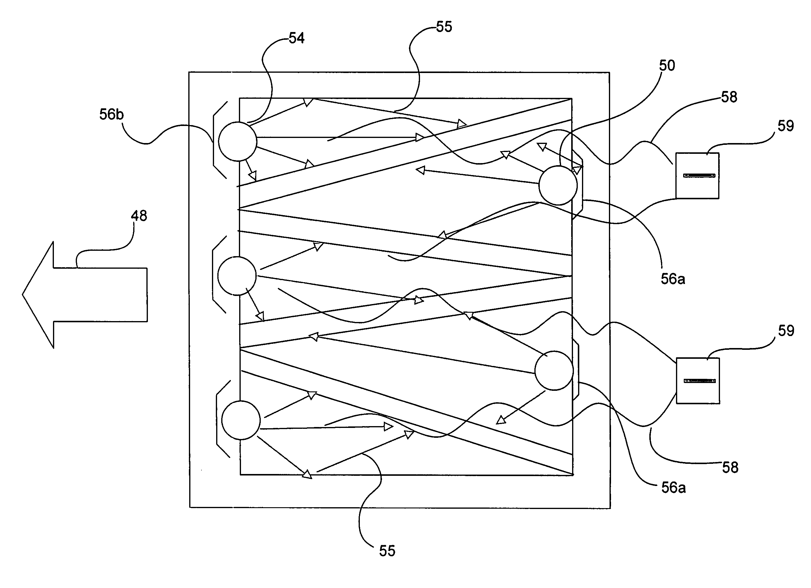
[0045]FIG. 1 is a cross sectional schematic representation of a decontamination unit 10 including a filter 12, in accordance with an embodiment of the invention. FIG. 2 is a top cross sectional schematic view of the decontamination unit 10 of FIG. 1. The decontamination unit 10 comprises a housing 14 with a top wall 16, a bottom wall 18, two side walls 20 and 22, a front wall 24 and a back wall 26. An air inlet 28 and an air outlet 30 are defined in the housing 14, in this example in the front wall 24 and the back wall 26. The air inlet 28 and / or the air outlet 30 may be defined in other walls, instead. The housing 14 and structures within the housing define an air path A between the inlet 28 and the outlet 30. The housing 14 is preferably air tight, except for the air inlet 28, the air outlet 30, and optional air sampling ports 72 discussed further, below. The walls of the housing 14 are preferably steel. At least one wall should be removable or hinged to facilitate opening so that...


PUM

PropertyMeasurementUnit
sizeaaaaaaaaaa
sizeaaaaaaaaaa
wavelength rangeaaaaaaaaaa

Abstract

Air decontamination devices in one example include a filter directly exposed to ultraviolet (“UV”) radiation on an upstream side and a downstream side. Ozone may be provided to permeate the filter, as well. Reflectors may be provided to reflect UV radiation emitted in a direction away from the filter, towards the filter. The filter may be a V-bank filter, for example. Air sampling ports and prefilters may be provided. The air decontamination units may be used to decontaminate the air after industrial and medical contaminations and terrorist biological, chemical and radiological attacks, for example. Mobile isolation units, and methods of decontaminating rooms, are disclosed, as well.

Description

[0001]The present application claims the benefit under 35 U.S.C. § 119(e) of U.S. Provisional Patent Application No. 60 / 382,126 filed on May 20, 2002, which is incorporated by reference, herein.FIELD OF INVENTION[0002]Air filtration devices and, more particularly, germicidal air filters, decontamination devices and mobile isolation units.BACKGROUND OF INVENTION[0003]Decontamination devices have typically been designed to filter, irradiate, and / or trap irritants or infectious agents, such as bacteria, viruses, mold and other microorganisms, in air. Such irritants and infectious agents may contaminate the air due to industrial accidents, fires, an infected individual, or a chemical or biological terrorist attack, for example. Decontamination devices typically comprise a chamber to expose contaminated air to ultraviolet (“UV”) radiation followed by a filter. The filter may be a high efficiency particle arrester (“HEPA”) filter.[0004]Ultraviolet irradiation in prior art devices is typic...

Claims


Application Information

Patent Timeline
Patent Type & Authority Patents(United States)
IPC IPC(8): B01J19/08A61L2/10A61L2/20A61L9/015A61L9/16A61L9/20B01D46/00B01D46/42F24F8/22F24F8/26
CPCA61L2/10A61L9/015A61L9/16A61L9/20B01D46/10B01D46/125F24F3/16A61L2/202Y02B30/78B01D2279/65F24F11/0017F24F2003/1614F24F2003/1621F24F2003/1625F24F2003/1667F24F2003/1685F24F2221/125F24F2221/44F24F11/30F24F2110/50F24F8/15F24F8/158F24F8/108F24F8/22F24F8/40Y02B30/70B01D46/121B01D2257/708B01D2259/4508B01D2259/804B01D53/007F24F8/26
Inventor ARTS, THEODORE A. M.THOMSEN, JAMES M.CHIRAYATH, PAUL J.SCHENTAG, JEROME
Owner AUSTIN AIR SYST
Why Eureka
Try Eureka