
Electronic power circuit

Inactive Publication Date: 2008-02-05
SIEMENS AG
View PDF13 Cites 23 Cited by
  • Summary
  • Abstract
  • Description
  • Claims
  • Application Information

AI Technical Summary

Benefits of technology

[0011]The self-conducting power semiconductor further reduces the forward losses and switching losses of the electronic power circuit. Since the number of semiconductor chips is reduced by 50% as compared to hybrid power MOSFET's, this electronic power circuit also requires less installation space and is more cost-effective than an electronic power circuit with hybrid power MOSFET's. To operate the electronic power circuit with self-conducting power semiconductors, the accessory device connected before the power supply should be configured so that the power supply can be supplied with a predetermined supply voltage for the trigger device of the self-conducting power semiconductor immediately after a power switch is closed. In this case, the electronic power circuit can be switched on by blocking the self-conducting power semiconductor of the electronic power circuit. This results in an electronic power circuit which operates like an electronic power circuit with self-blocking power semiconductors, accompanied by significantly reduced forward losses and switching losses.
[0012]According to an advantageous feature of the invention, the self-conducting power semiconductor is a junction-FET (JFET) with a high blocking voltage which can be made of silicon carbide. This power semiconductor switch can be operated at a high-temperature, and significantly less heat is dissipated than with conventional electronic power circuits. As a result, the electronic power circuit requires less installation space. In addition, the electronic power circuit according to the invention can be placed in direct proximity of devices or even inside devices that dissipate heat. Accordingly, an electronic power circuit according to the invention can be integrated in a terminal box of an electric motor without requiring a dedicated heat removal device.
[0013]According to another advantageous feature of the invention, the self-conducting power semiconductor is constructed so as to have a saturating characteristic which limits a current flow through the self-conducting power semiconductor independent of an applied voltage. The self-conducting power semiconductor can be made of silicon carbide. When using such self-conducting power semiconductor, a separate accessory device for powering the trigger device of the self-conducting power semiconductor can be eliminated. As a result, the forward losses of an electronic power circuit can be reduced simply by replacing the self-blocking power semiconductor with a self-conducting power semiconductor.

Problems solved by technology

The self-blocking design of the semiconductors can require a fairly high forward voltage, which during operation can cause forward losses as well as switching losses.
This increases the required installation space for an electronic power circuit; moreover, electronic power circuits may therefore not be installed in close proximity of other devices that dissipate heat.
The forward losses and switching losses increase with the voltage applied to the power semiconductor.
This not only increases the space requirement of the electronic power circuit, but also its cost.

Method used


Image

  • Electronic power circuit
  • Electronic power circuit
  • Electronic power circuit

Examples


Embodiment Construction

[0030]Throughout all the Figures, same or corresponding elements are generally indicated by same reference numerals. These depicted embodiments are to be understood as illustrative of the invention and not as limiting in any way.

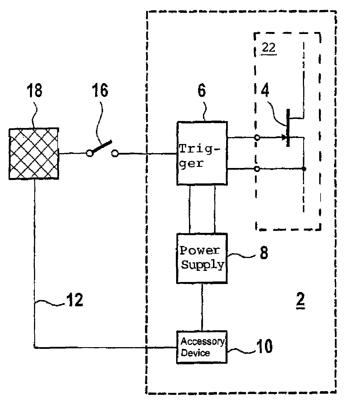
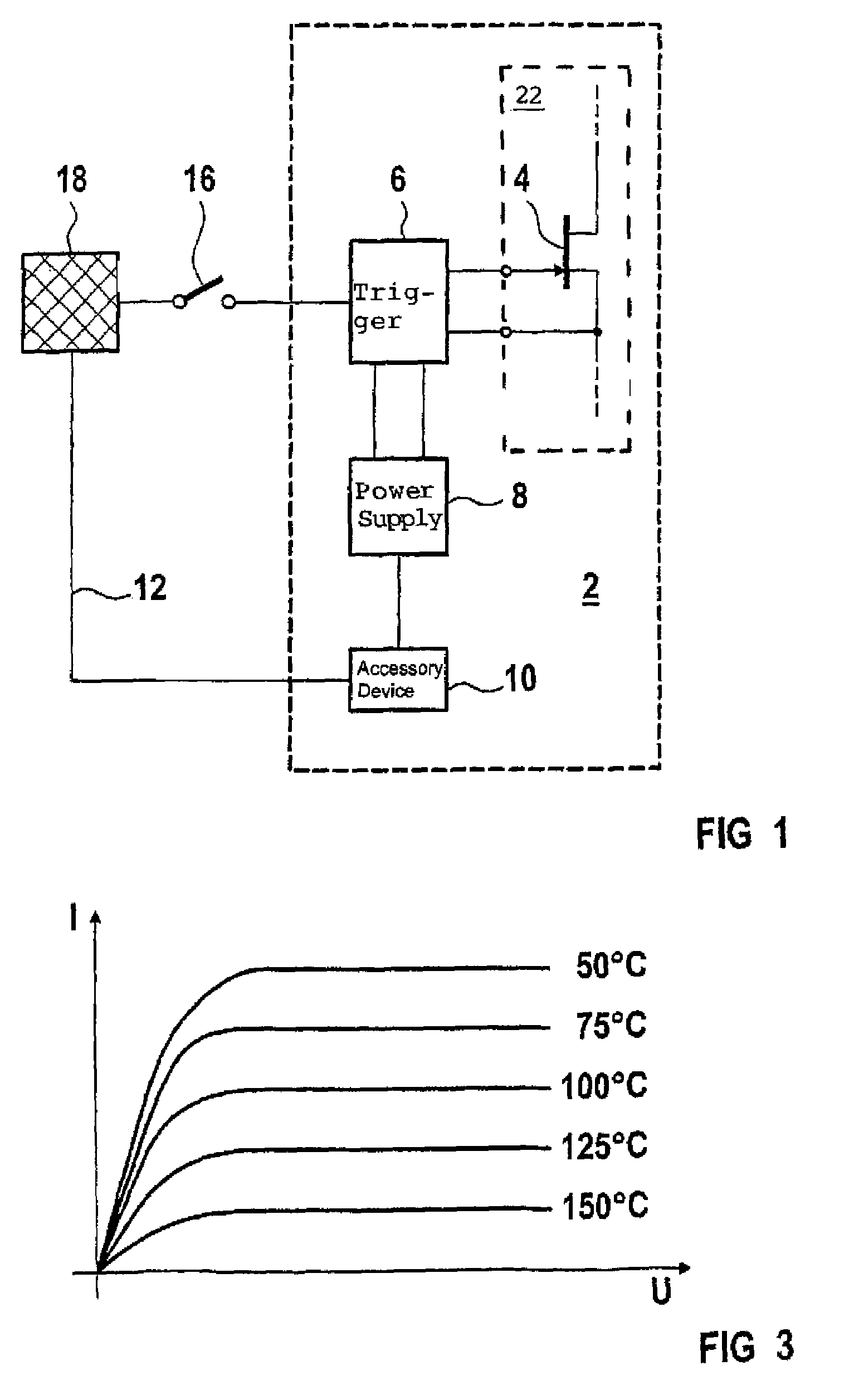
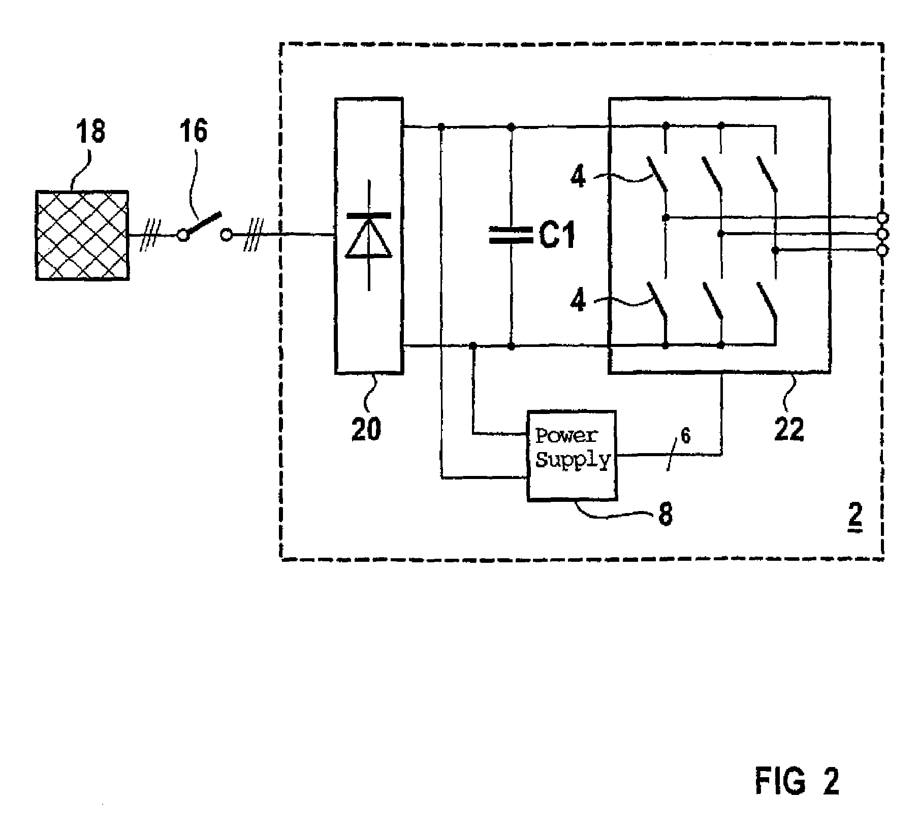
[0031]Turning now to the drawing, and in particular to FIG. 1, there is shown a first embodiment of an electronic power circuit 2 according to the present invention. The electronic power circuit 2 includes at least one self-conducting power semiconductor 4, whose control inputs are connected to a corresponding trigger device 6. The electronic power circuit 2 also includes a power supply 8 for the trigger device 6 and an accessory device 10. The output side of the accessory device 10 is connected to terminals of the power supply 8 of the trigger device 6. In addition, the accessory device 10 is connected to a power grid or network 18 via a line 12. The electronic power circuit 2 can be connected to the network 18 with the help of an ON / OFF switch. The self-co...


PUM


Abstract

An electronic power circuit includes at least one power semiconductor whose control inputs are connected to a trigger device and a power supply which, on the output side, is connected to terminals of the trigger device and, on the input side, is connected to an accessory device to which a supply voltage is applied. The power semiconductor is implemented as a self-conducting power semiconductor, which economically reduces the forward power losses and switching losses of an electronic power circuit.

Description

CROSS-REFERENCES TO RELATED APPLICATIONS[0001]This application is a continuation of prior filed copending PCT International Application No. PCT / DE01 / 04486, filed Nov. 29, 2001, on which priority is claimed under 35 U.S.C. § 120, the disclosure of which is hereby incorporated by reference.[0002]This application claims the priority of German Patent Application, Serial No. 100 63 084.7, filed Dec. 18, 2000, pursuant to 35 U.S.C. 119(a)-(d), the disclosure of which is incorporated herein by reference.BACKGROUND OF THE INVENTION[0003]The invention relates to an electronic power circuit, and more particularly to an electronic power circuit with low forward and switching losses for a trigger device.[0004]Among electronic power circuits are converter circuits, such as a self-commutated converter which can be operated as an inverter or a rectifier, or a DC / DC converter which can be implemented as a buck converter and / or a boost converter or as part of a switched mode power supply. All these ...

Claims


Application Information

Patent Timeline
IPC IPC(8): G05F1/10G05F3/02H01H83/18H02H7/00H02M7/537H03K17/687
CPCH02M7/537H03K17/687H03K2017/6875H01L2924/0002H01L2924/00
Inventor ECKARDT, DIETERREBBEREH, CARSTENSCHIERLING, HUBERTWEIS, BENNO
Owner SIEMENS AG
Learn More