Microvoided light diffuser

a diffuser and micro-void technology, applied in mechanical devices, lighting and heating devices, instruments, etc., can solve the problems of lowering the efficiency of the optical system, high backscattering, and the need for air contact, and achieve the effect of improving the light transmission

Inactive Publication Date: 2008-02-05
SKC HI TECH & MARKETING CO LTD CO REGISTRATION NO 161511 0225312
View PDF12 Cites 41 Cited by
  • Summary
  • Abstract
  • Description
  • Claims
  • Application Information

AI Technical Summary

Benefits of technology

[0014]The invention provides improved light transmission while simultaneously diffusing specular light sources.

Problems solved by technology

However, some prior art light diffusers of this type suffer from two major drawbacks: a high degree of backscattering and the need for air contact.
Backscattering causes reflection of a significant portion of the light back to the originating source when it should properly pass through the diffuser, lowering the efficiency of the optical system.
The second drawback, the requirement that the rough surface must be in contact with air to operate properly, may also result in lower efficiency.
Bulk diffusers also present some practical problems.
If however the bulk diffuser is made thin, a desirable property for most applications, the scattering ability of the diffuser may be too low.
While the voided layer described in U.S. Pat. No. 6,093,521 does diffuse back illumination utilized in prior art light boxes used to illuminate static images, the percent transmission between 38 and 42% would not allow a enough light to reach an observers eye for a liquid crystal display.
Further, the addition of white pigment to the sheet causes unacceptable scattering of the back light.
While the materials and methods disclosed in this patent are suitable for reflective photographic products, the % light energy transmission (less than 40%) is not suitable for liquid crystal display as % light transmission less than 40% would unacceptable reduce the brightness of the LC device.
While the materials disclosed in U.S. Pat. No. 4,912,333 are transmissive for X-ray energy, the materials have a very low visible light energy transmission which is unacceptable for LC devices.
The aspect ratio of these materials, while shaping incident light, expanding the viewing angle, do not provide uniform diffusion of light and would cause uneven lighting of a liquid crystal formed image.
Further, the disclosed method for creating voids results in void size and void distribution that would not allow for optimization of light diffusion and light transmission.
Such values are unacceptable for any diffusion film useful for image display, such as a liquid crystal display.

Method used


Image

  • Microvoided light diffuser
  • Microvoided light diffuser
  • Microvoided light diffuser

Examples


example 1

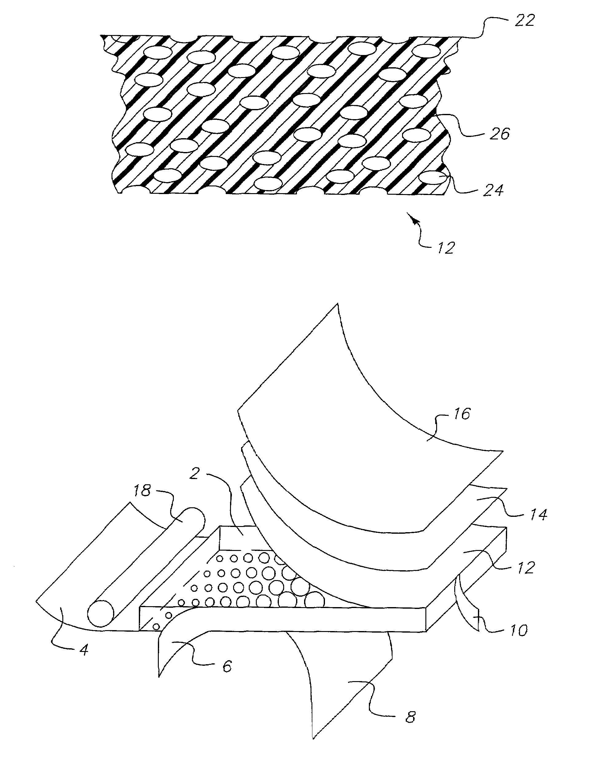
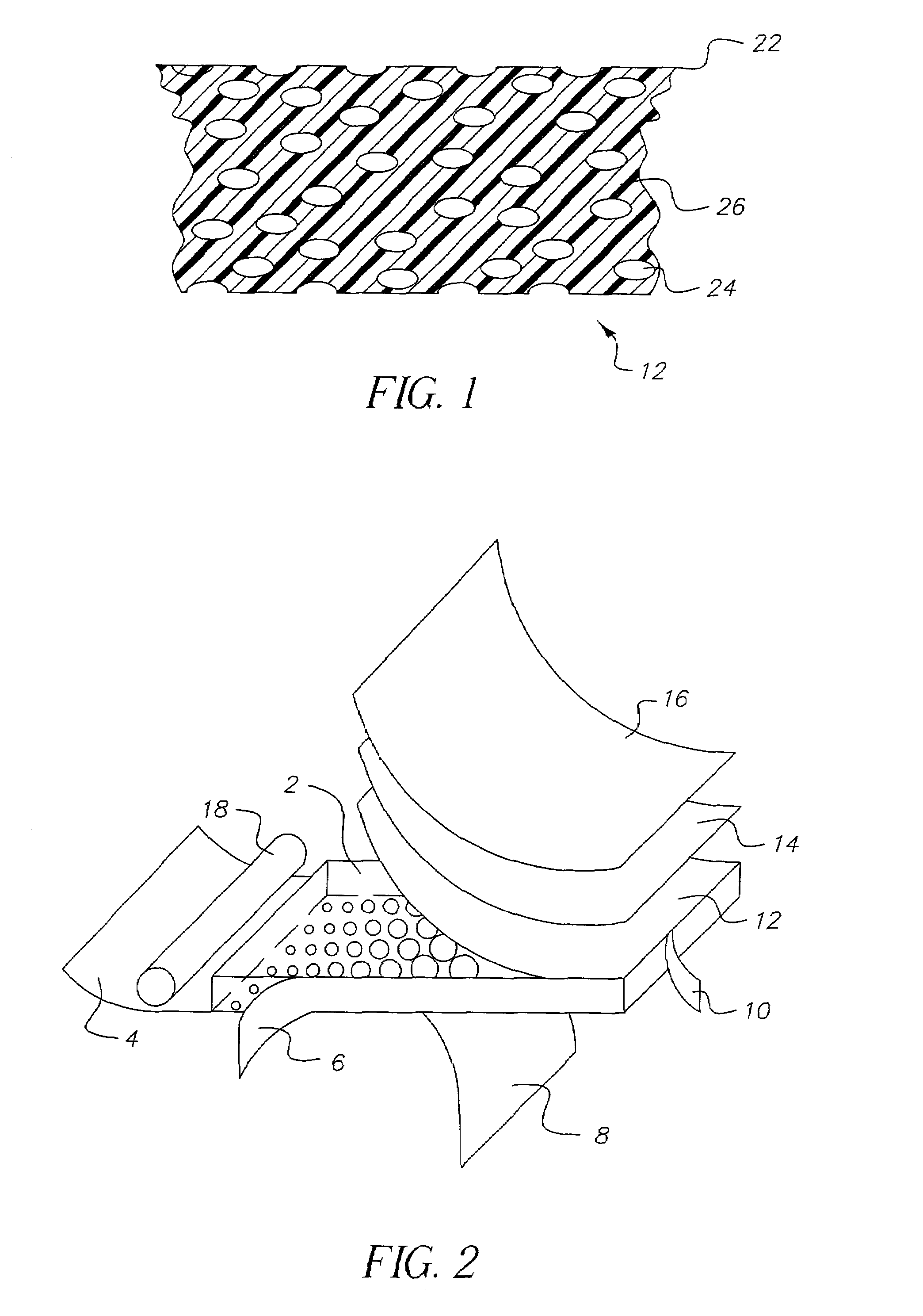
[0082]A transparent amorphous film composed of two layers having an overall width of 16 cm was manufactured by a co-extrusion process. One of the layers, hereafter referred to as layer (A), was composed of poly(ethylene terephthalate) (“PET”, commercially available from Eastman Chemical Company as Eastapak #7352). The intrinsic viscosity (I.V.) of the PET 7352 resin was 0.74. This layer was 737-864 μm in thickness. The other layer, hereafter referred to as layer (B), was composed of PET (commercially available from Eastman Chemical Company as Eastapak #9921) impregnated with a voiding agent. The intrinsic viscosity (I.V.) of the PET 9921 resin was 0.80. This layer was 25-152 μm in thickness.

[0083]The voiding agent was created as follows. A 27 mm twin screw compounding extruder heated to 275° C. was used to mix polystyrene beads cross-linked with divinylbenzene with PET 9921. The beads had an average particle diameter of 2 μm. The beads were added to attain a 20% by weight loading in...

example 2

[0086]A transparent amorphous film composed of two layers having an overall width of 16 cm was manufactured by a co-extrusion process as described in Example 1. Layer (A), composed of PET 7352, was 838 μm in thickness. Layer (B), composed of PET 9921 impregnated with cross-linked polystyrene as a voiding agent, was 51 μm in thickness. The polymers composing the layers were processed as described in Example 1.

[0087]The amorphous cast sheet was stretched symmetrically in a similar fashion as described in Example 1. The sheet was stretched symmetrically in the X and Y-directions to an extent of 3 times the original sheet dimensions. The sheet temperature during stretching was 105° C. The processing conditions are shown in Table 1.

example 3

[0088]A transparent amorphous film composed of two layers having an overall width of 16 cm was manufactured by a co-extrusion process as described in Example 1. Layer (A), composed of PET 7352, was 838 μm in thickness. Layer (B), composed of PET 9921 impregnated with cross-linked polystyrene as a voiding agent, was 51 μm in thickness. The polymers composing the layers were processed as described in Example 1.

[0089]The amorphous cast sheet was stretched symmetrically in a similar fashion as described in Example 1. The sheet was stretched symmetrically in the X and Y-directions to an extent of 4 times the original sheet dimensions. The sheet temperature during stretching was 105° C. The processing conditions are shown in Table 1.


PUM

PropertyMeasurementUnit
thicknessaaaaaaaaaa
elastic modulusaaaaaaaaaa
average volumeaaaaaaaaaa

Abstract

The invention relates to a light diffuser comprising a thermoplastic layer containing thermoplastic polymeric material and microvoids having a substantially circular cross-section in a plane perpendicular to the direction of light travel and having a diffuse light transmission efficiency of at least 65%.

Description

CROSS REFERENCE TO RELATED APPLICATIONS[0001]This application is related to three applications co-filed herewith under U.S. Ser. No. 10 / 017,002, U.S. Ser. No. 10 / 020,404, and U.S. Ser. No. 10 / 020,714, the contents of which are incorporated herein by reference.FIELD OF THE INVENTION[0002]The invention relates to a diffuser for specular light. In a preferred form, the invention relates to a back light diffuser for rear projection liquid crystal display devices.BACKGROUND OF THE INVENTION[0003]Optical structures that scatter or diffuse light generally function in one of two ways: (a) as a surface diffuser utilizing surface roughness to refract or scatter light in a number of directions; or (b) as a bulk diffuser having flat surfaces and embedded light-scattering elements.[0004]A diffuser of the former kind is normally utilized with its rough surface exposed to air, affording the largest possible difference in index of refraction between the material of the diffuser and the surrounding ...

Claims


Application Information

Patent Timeline
Patent Type & Authority Patents(United States)
IPC IPC(8): G02F1/1335G02B13/20F21V3/04F21V8/00F21Y103/00G02B5/02G02F1/13357
CPCG02B5/0242G02B5/0247G02B5/0278F21V3/04G02F1/133504
Inventor BRICKEY, MICHAEL R.KAMINSKY, CHERYL J.BOURDELAIS, ROBERT P.LANEY, THOMAS M.
Owner SKC HI TECH & MARKETING CO LTD CO REGISTRATION NO 161511 0225312
Why Eureka
Try Eureka