CPP giant magnetoresistive head with large-area metal film provided between shield and element

Inactive Publication Date: 2008-02-05
TDK CORPARATION
View PDF20 Cites 17 Cited by
  • Summary
  • Abstract
  • Description
  • Claims
  • Application Information

AI Technical Summary

Benefits of technology

[0027]In the present invention, the large-area nonmagnetic metal films are provided directly above the lower shield layer and below the upper shield layer, respectively, and have a constant thickness and larger areas than those of the free magnetic layer and the pinned magnetic layer, respectively, and thus the concentration of the sensing current in the upper and lower shield layers can be relieved to decrease noise due to the AMR effect of the upper and lower shield layers.
[0028]Also, in the present invention, the antiferromagnetic layer is provided in the rear of the giant magnetoresistive element in the height direction, for pinning the magnetization directi

Problems solved by technology

The change in resistance becomes noise of the output of the head.
Particularly, with a high current density, there is the problem of increasing the noise due to the AMR effect.
However, a sufficient magnetic shield effect cannot be obtained by using the shield material with a low AMR effect.
Since the temperature of the whole of the he

Method used


Image

  • CPP giant magnetoresistive head with large-area metal film provided between shield and element
  • CPP giant magnetoresistive head with large-area metal film provided between shield and element
  • CPP giant magnetoresistive head with large-area metal film provided between shield and element

Examples


Embodiment Construction

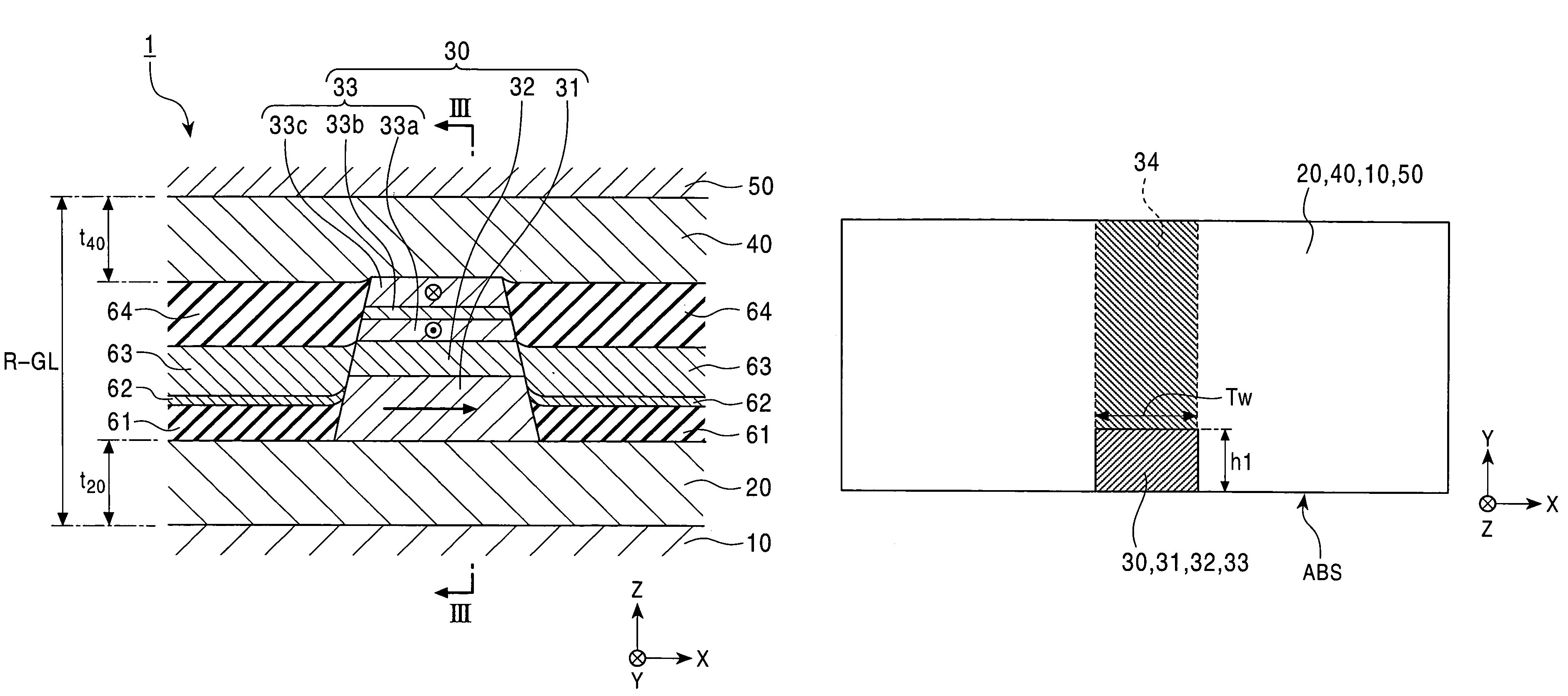
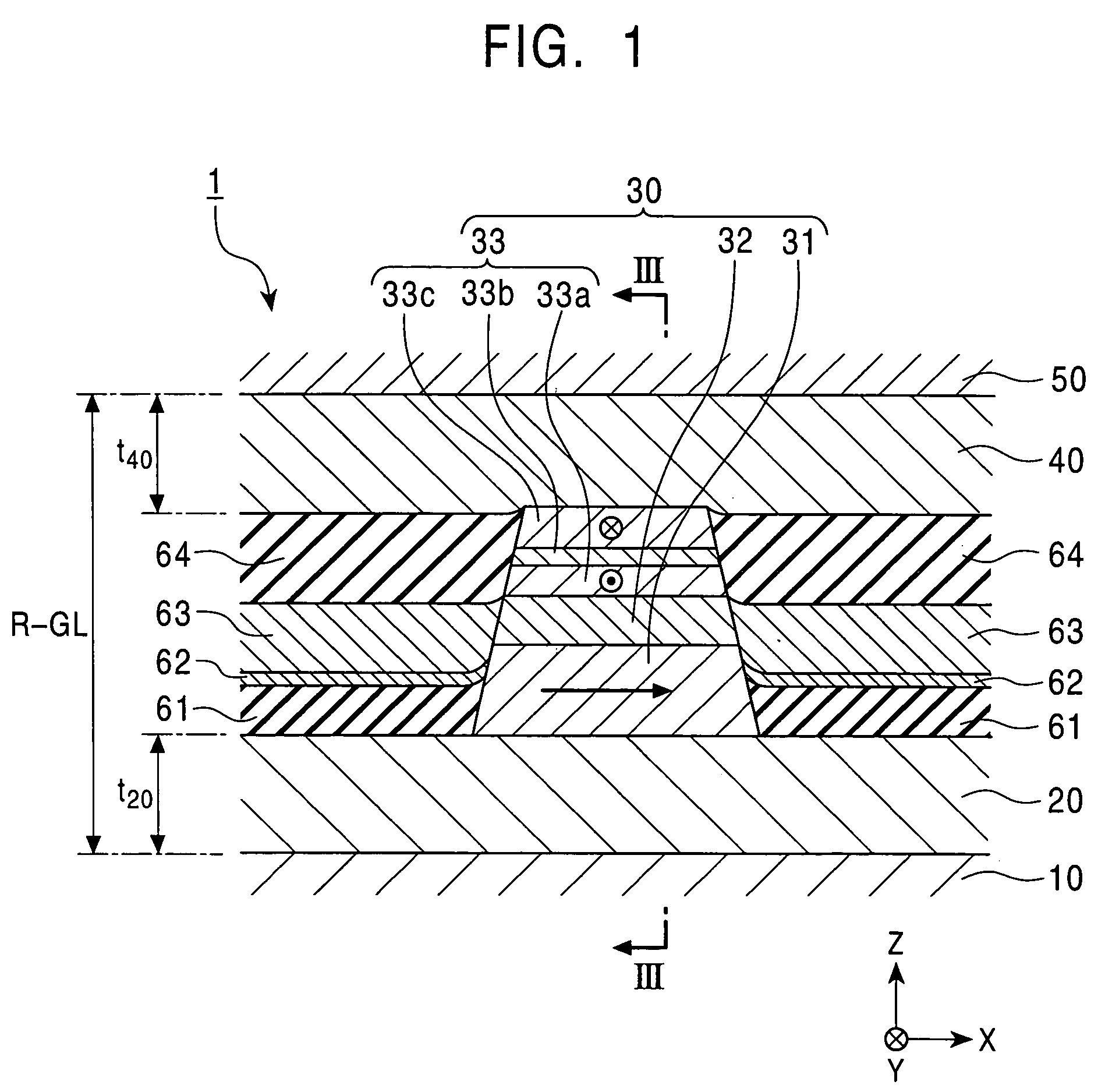
[0037]The present invention will be described below with reference to the drawings. In each of the drawings, the X direction corresponds to the track width direction, the Y direction corresponds to the direction of a leakage magnetic field from a recording medium, and the Z direction corresponds to the moving direction of the recording medium and the lamination direction of layers which constitute a giant magnetoresistive element.

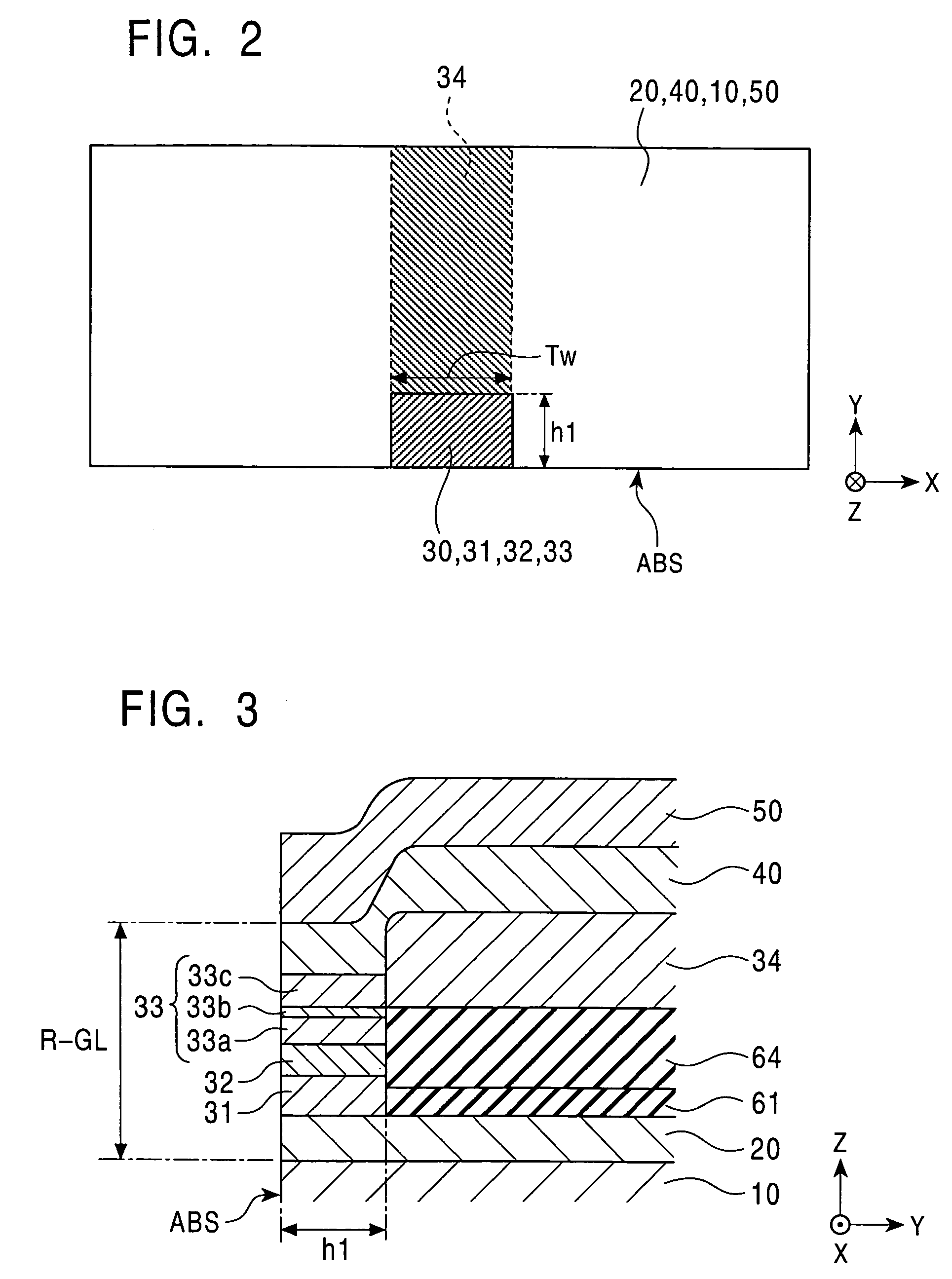
[0038]FIGS. 1 to 5 show a CPP giant magnetoresistive head (CPP-GMR head) according to a first embodiment of the present invention. FIG. 1 is a partial sectional view showing the structure of a CPP-GMR head 1, as viewed from the surface facing the recording medium, and FIG. 2 is a schematic top plan view of a GMR element 30, and FIG. 3 is a partial sectional view showing the structure of the CPP-GMR head 1, taken along a central line (line III-III in FIG. 1) of the element.

[0039]The CPP-GMR head 1 comprises lower and upper shield layers 10 and 50 with a pred...


PUM


Abstract

A CPP giant magnetoresistive (GMR) head includes lower and upper shield layers; and a GMR element disposed between the upper and lower shield layers and comprising a pinned magnetic layer, a free magnetic layer, and a nonmagnetic layer disposed between the pinned magnetic layer and the free magnetic layer. Nonmagnetic metal films are provided directly above the lower shield layer and below the upper shield layer making direct contact with and having larger areas than the pinned magnetic layer and the free magnetic layer, respectively. An antiferromagnetic layer is provided in the rear of the GMR element in the height direction, for pinning the magnetization direction of the pinned magnetic layer. Alternatively, the dimension of the pinned magnetic layer in the height direction is larger than the dimension in the track width direction so that the magnetization direction of the pinned magnetic layer is stabilized without using an antiferromagnetic layer.

Description

[0001]This application claims the benefit of priority to Japanese Patent Application Nos. 2003-114189 and 2004-047758, herein incorporated by reference.BACKGROUND OF THE INVENTION[0002]1. Field of the Invention[0003]The present invention relates to a CPP (Current Perpendicular to the Plane) giant magnetoresistive head in which a sensing current flows in the thickness direction (perpendicularly to the film plane).[0004]2. Description of the Related Art[0005]Giant magnetoresistive (GMR) elements used for hard disk devices and magnetic sensors are roughly divided into a CIP (Current in the Plane) type in which a sensing current flows in parallel with the film plane of each of layers constituting an element, and a CPP (Current Perpendicular to the Plane) type in which a sensing current flows perpendicularly to the film plane of each of the layers constituting an element.[0006]FIG. 8 is a longitudinal sectional view showing the structure of a CPP-GMR head using a conventional CPP-GMR ele...

Claims


Application Information

Patent Timeline
IPC IPC(8): G11B5/39G11B5/31G11B5/40H01F10/16H01F10/32H01L43/08H01L43/10
CPCG11B5/3903G11B5/3932G11B5/3116G11B5/313G11B5/3967G11B5/40
Inventor SAITO, MASAMICHI
Owner TDK CORPARATION
Why Eureka
Try Eureka