
Apparatus and method for freezing the states of a receiver during silent line state operation of a network device

a network device and receiver technology, applied in the field of communication links, can solve the problem that the receiver may not know the phase of incoming data immediately, and achieve the effect of reducing the power required by a lan communication link, preventing data loss, and reducing the power of the physical layer devi

Inactive Publication Date: 2008-02-05
MAXIM INTEGRATED PROD INC
View PDF12 Cites 87 Cited by
  • Summary
  • Abstract
  • Description
  • Claims
  • Application Information

AI Technical Summary

Benefits of technology

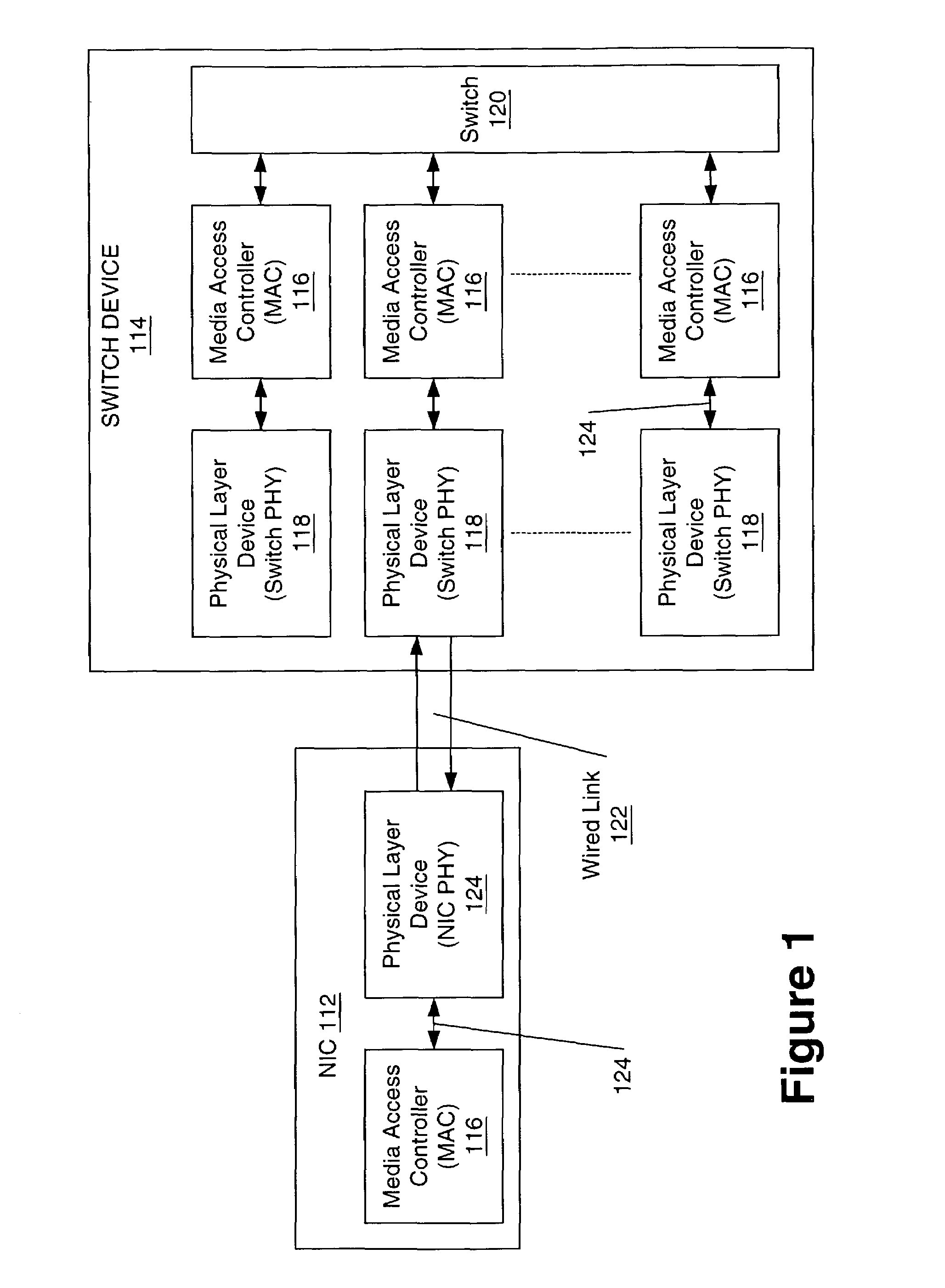
[0070]Accordingly, it is an object of an embodiment of the invention to provide network devices having a full power operational mode for supporting the high-bandwidth communication requirement of the standard protocol (e.g., IEEE 802.3), and a low power “link-suspend” operational mode of operation when only limited communication is occurring, such as when there are fewer data packets being transmitted across the link. The low power “link-suspend” (LS) mode reduces the power required by a LAN communications link at the physical layer by transmitting low duty cycle “link-suspend-packets” (LSPs) instead of continuous idle pulses or symbols during non-data communication periods. LSPs are sent between periods of Silent Line State (SLS) to prevent the link from resetting. During the SLS, which is a non-data transmission period, the transmitter power may be turned off to conserve power and then turned back on when there is need to transmit LSPs or data. By turning transmitter power off with a low duty cycle, i.e., between LSP transmissions, the present invention substantially reduces physical layer device (PHY) power.
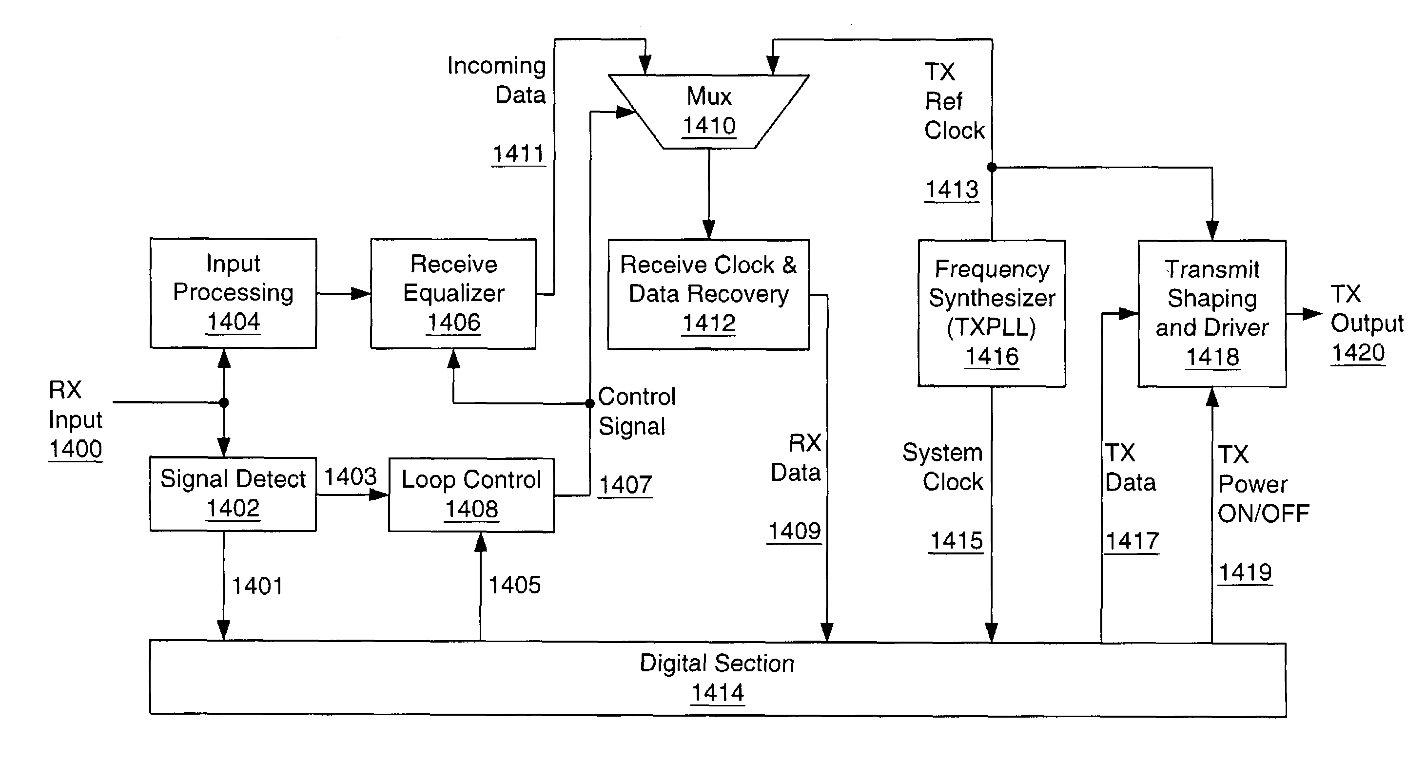
[0071]In embodiments of the invention, the receiver states are frozen during SLS using methods that avoid parasitic decay. Also, the receive clock phase lock loop (RXPLL) is locked onto the local transmit clock since the local transmit clock has a frequency approximating the incoming data frequency. However, during SLS, which is a non-data transmission period, the receiver may not immediately know the phase of incoming data. Thus, in order to prevent loss of data, the receiver loops of the receiving network device are periodically trained to the frequency of the transmitting remote network device by the periodic LSPs. Thus, although the RXPLL may not be immediately in phase with the input data, since the frequency is approximately the same only the phase need be acquired when data arrives. In one or more embodiments, the phase is quickly acquired using loop bandwidth shift methods whereby the receive clock phase lock loop bandwidth is increased to a value that aids rapid acquisition of the input clock and then, after acquisition, the bandwidth is shifted to a low value to enhance noise rejection during tracking.
[0072]Link Suspend Packets are used to maintain the communication link between the link partners. In addition, they provide enough information for the link suspended devices (e.g., PHYs in SLS) to train the receiver loops in order to rapidly lock onto the incoming signal and effectively receive the data. According to an embodiment of the invention, an LSP begins with an unscrambled, predetermined and / or predictable preamble. The use of an LSP with an unscrambled and known preamble allows for easy detection of LSPs. The LSP may also include a scrambled idle sequence, followed by a termination symbol sequence. The termination symbol sequence is preferably not a symbol sequence used by the standard protocol. The scrambled idle sequence provides adequate time for the receiver loops to stabilize in preparation for entering silent line state. In one or more embodiments, LSPs are specially constructed so that they serve as part of the data preamble when the network devices are operating in the link suspend mode. Therefore, the nature of the LSPs is that they are compatible with the standard protocol requirement for data transmission.
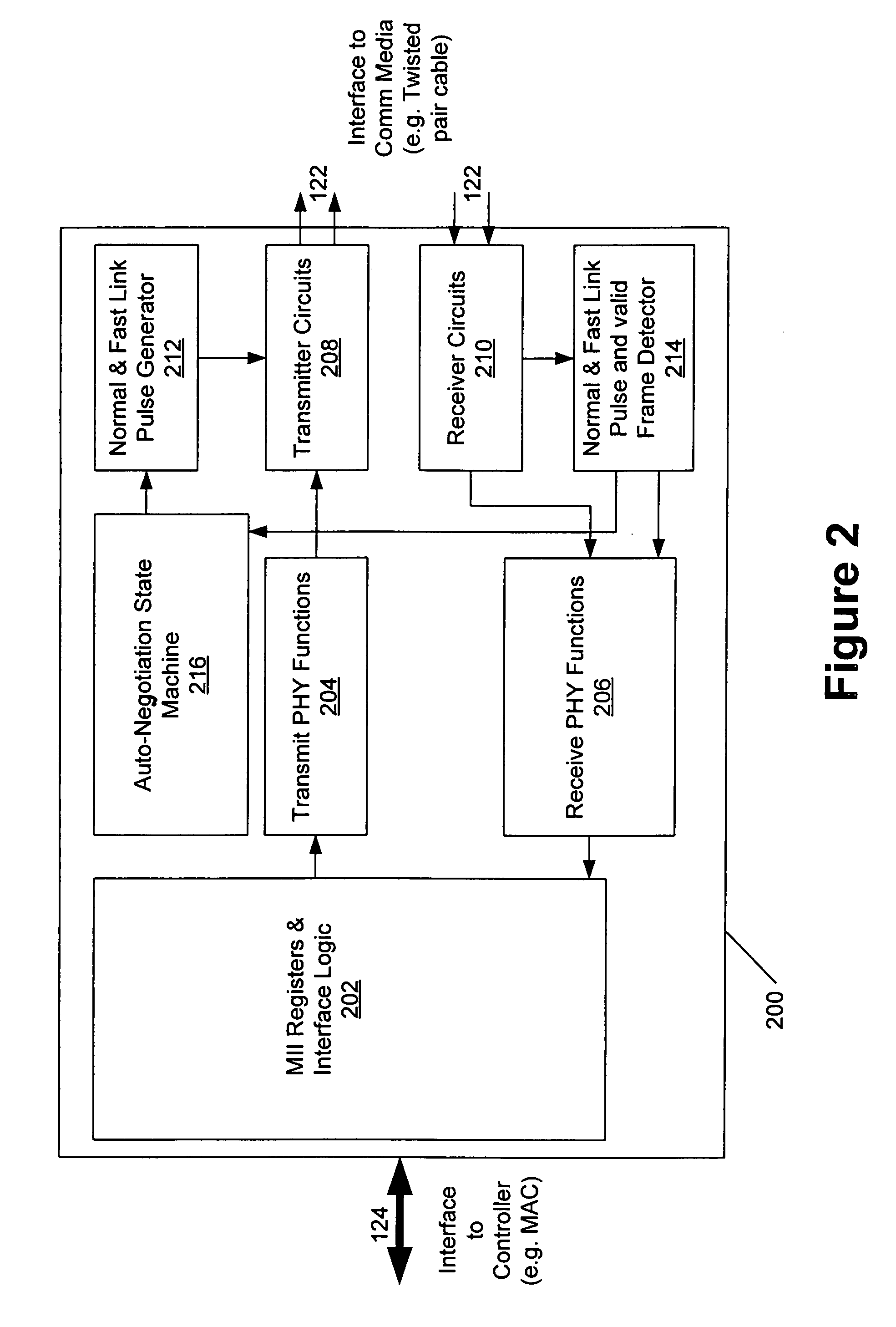
[0073]In one embodiment, a link suspend capable PHY may be connected to an existing network of PHY devices without any change to the existing network or devices. An LS capable PHY of the present invention also operates in the standard protocol mode (e.g., IEEE 802.3) of the other network devices. Data communicated to an LS capable PHY operating in either the LS mode or the standard protocol mode may not be lost so long as the link is maintained. Thus, incorporating an LS capable PHY into an existing network of LS capable and / or non-LS capable PHYs is transparent. Operation in LS mode is negotiated between an LS capable PHY and a remote PHY that is also LS capable. One embodiment supports negotiation with a remote link partner to set up LS mode by advertising operational mode capabilities between the two network devices. Negotiation allows a PHY to easily detect whether it is connected to another LS mode capable PHY in order to initiate communication in LS mode. An LS capable PHY may transmit and / or receive in LS mode. Transmitting in LS mode is not negotiated. Thus, a PHY operating in LS mode may unilaterally disable the ability to transmit in LS mode and communication will not be lost since the partner PHY is capable of receiving in either mode.
[0074]One aspect of the invention, in accordance with an embodiment, provides a PHY capable of transmitting and receiving valid data frames when network nodes are in LS, sleep, WOL, or link suspend mode. Thus, the invention is able to return to a full communications state, from a sleep or suspend state without missing any incoming data.

Problems solved by technology

However, during SLS, which is a non-data transmission period, the receiver may not immediately know the phase of incoming data.

Method used


Image

  • Apparatus and method for freezing the states of a receiver during silent line state operation of a network device
  • Apparatus and method for freezing the states of a receiver during silent line state operation of a network device
  • Apparatus and method for freezing the states of a receiver during silent line state operation of a network device

Examples


Embodiment Construction

[0093]The present invention is a method and apparatus for freezing the states of a receiver during silent line state operation of a network device. In the following description, numerous specific details are set forth to provide a more thorough description of the present invention. It will be apparent, however, to one skilled in the art, that the present invention may be practiced without these specific details. In other instances, well known features have not been described in detail so as not to obscure the present invention. Hereinafter, the term “system” is used to refer to a device and / or a method for performing a function. Also, hereinafter the term “network device”, “network node”, “physical layer device” or “PHY” is used to refer to a network apparatus, network device, network interface card (NIC), network node, network hub, a computer linked to a network via a network interface card, voice over Internet Protocol systems, LAN telephone systems, or refers to other devices tha...


PUM


Abstract

A method for maintaining the states of a receiver during the silent line state of a network device operating in a low power link suspend mode is presented. Accordingly, a method of freezing the states of the equalizer and keeping the receiver clock locked to a frequency that is approximately equal to that of the input data while providing for rapid adjustment to the phase and thus recovery of the input data is presented. During Silent Line State (SLS), the receiver states are frozen using methods that avoid parasitic decay. Also, the receive clock phase lock loop is locked onto the local transmit clock since the local transmit clock has a frequency approximating the incoming data frequency. During the SLS, the transmitter of the remote network device may have been turned off to conserve power therefore the receiver has no way of immediately knowing the phase of an incoming data. Thus, in order to prevent loss of data, the receiver loops of the receiving network device are trained to the frequency of the transmitting remote network device using periodic Link Suspend packets. Thus, in most cases, only the phase of the incoming signal need be acquired when data arrives. The phase may be quickly acquired using loop bandwidth shift methods whereby the receive clock phase lock loop bandwidth is increased to a value that aids rapid acquisition of the input clock and then, after acquisition, the bandwidth is shifted to a low value to enhance noise rejection during tracking.

Description

[0001]This application claims priority of U.S. Provisional Application No. 60 / 381,062 filed on May 15, 2002, entitled “Method for Freezing the States of a Receiver During Silent Line State Operation of a Network Device,” and of U.S. Provisional Application No. 60 / 326,520 filed on Oct. 2, 2001, entitled “Method and Apparatus for Transparent Implementation of Link-Suspend Capabilities in Network Devices,” and is a Continuation-In-Part of U.S. application Ser. No. 09 / 676,040, filed on Sep. 28, 2000 now U.S. Pat. No. 6,795,450, entitled “Method and Apparatus for Supporting Physical Layer Link-Suspend Operation Between Network Devices,” the specifications of which are herein incorporated by reference.BACKGROUND OF THE INVENTION[0002]1. Field of the Invention[0003]This invention relates to the field of computer network point to point data communications, and more particularly to communications links that normally use constant idle bit streams between packet transmissions.[0004]2. Backgrou...

Claims


Application Information

Patent Timeline
IPC IPC(8): H04L12/66H04L12/12H04L29/06
CPCH04L12/12Y02B60/32Y02B60/34H04L69/24Y02B60/35Y02D30/50
Inventor MILLS, ANDREWANDERSSON, RALPHWORSHAM, ANTHONYNOOTBAAR, MICHAELROSKY, DAVIDBEHRIN, MICHAEL
Owner MAXIM INTEGRATED PROD INC
Learn More