
Method of conversion of continuous medium flow energy and device for conversion of continuous medium flow energy

Inactive Publication Date: 2008-02-19
INVENTORS NETWORK +1
View PDF24 Cites 11 Cited by
  • Summary
  • Abstract
  • Description
  • Claims
  • Application Information

AI Technical Summary

Benefits of technology

[0023]Contributing or positive vortices are vortices decreasing FI (inertial force) drag resistance or influencing a medium flow in a manner that said energy conversion is supported or increased. Often this type of vortices assists in generating an improved or smoothened flow or smoothened flow regimes which then is a basis for reduced losses during energy conversion or is restricted to boundary layers which then avoids an introduction of additional vortices in to a main flow.
[0090]The combined effect of the flow concentration and its suction due to the outflow from the second system and interaction with the external flow results in an increased energy conversion efficiency due to the reduction of losses, taking away of the flow by suction, as well as by the said interaction; in this case the speed of turbine rotation increases and its dimensions decrease due to the concentration of the streamlines or concentration of the velocity. In addition, the range of utilisation of the working flows running at a small velocity will extend, since the concentration of the velocity of these flows involves an increase of the velocity in the zone of location of the turbine. The stability of the flow provided by profiling of the system of channels in accordance with the natural shapes of the motion of natural vortex flows, as well as the smoothness of the velocity and pressure fields in the formed jets ensure reliable operation of the turbine and of the entire device as a whole due to the reduction of the nonstationary load effects in the construction.

Problems solved by technology

In addition, during the motion of the wind along the path of the device realising this or that energy conversion method as well as in the course of the interaction between the continuous medium flow and the elements of the said device, harmful secondary flows in the shape of vortices are generated, and some energy of the flow is spent on their formation; due to this fact, the flow is subject to an additional dynamic resistance which reduces the efficiency of conversion of its energy.
In other words, since harmful secondary vortex flows are generated in the flow against the background of the main flow during the interaction between the flow and the elements of the power generating plant or when the flow is moving along the path of the device, the efficiency of conversion was limited by the loss of energy on the formation of the vortices.
However, realisation of this method in the corresponding devices testifies to rather large losses, caused by the above-described absence of conditions, which are intended to ensure smooth joining of the stream-lines in the jets, flowing through the slots into the tornado tower, with the stream-lines in the formed tornado-like flow.
The disadvantage of the given energy conversion method and of the devices, based on this method, is that in this case the motion of the flow in the form of separate jets along the channels or volumes, into which this flow is directed, is characterised by nonstationary stream-lines, by their sharp bends and, as a consequence, by the formation of harmful secondary vortex flows involving energy losses by the flows and a low degree of efficiency of the device, by means of which the said method is realised.
The above method and device for its realisation have the following disadvantages: there is no axial swirling in the first system of trajectories and, therefore, the first system creates a rather weak reduced pressure in the area, delivered to which the flow is running out of the energy conversion zone; there is no description of the shape of the first system of channels, which could ensure high efficiency of energy conversion of the continuous medium flow in the said device.

Method used


Image

  • Method of conversion of continuous medium flow energy and device for conversion of continuous medium flow energy
  • Method of conversion of continuous medium flow energy and device for conversion of continuous medium flow energy
  • Method of conversion of continuous medium flow energy and device for conversion of continuous medium flow energy

Examples


Embodiment Construction

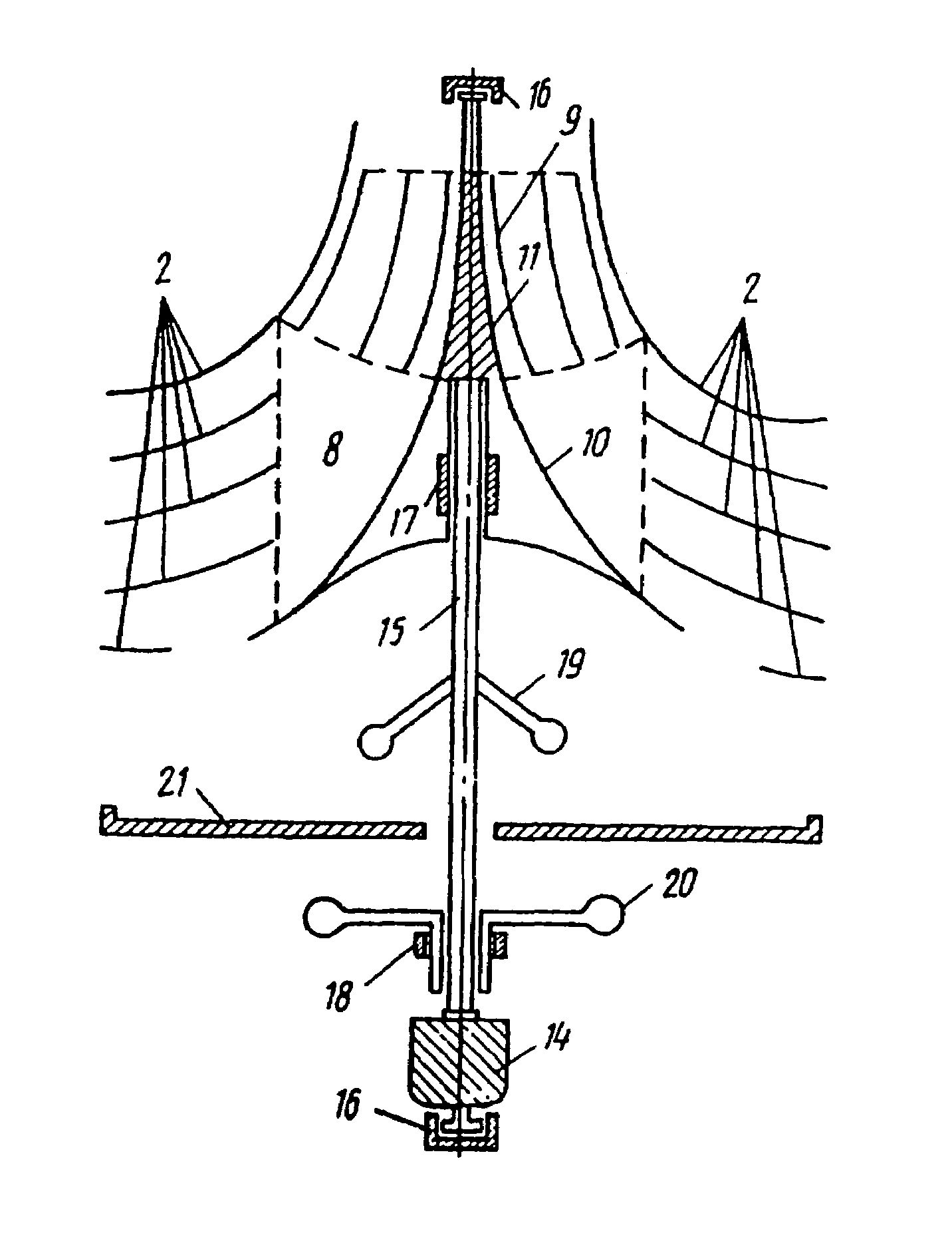
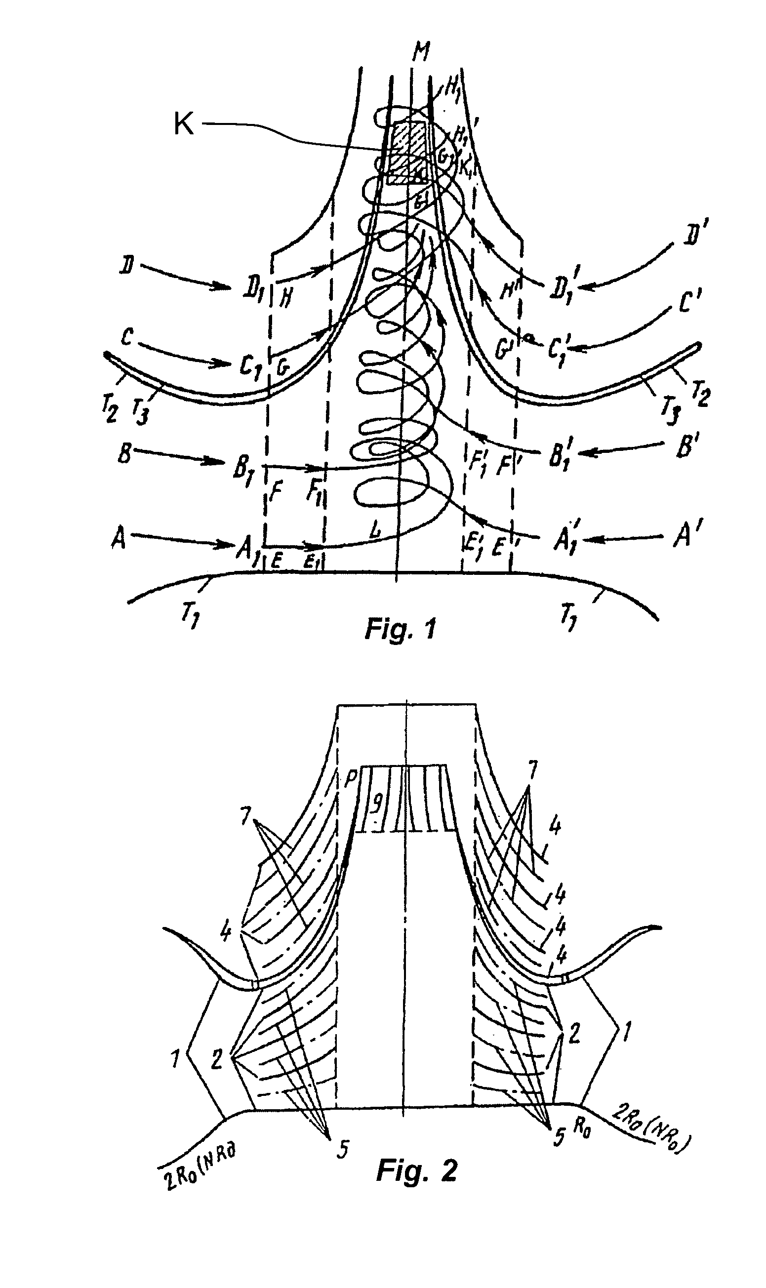
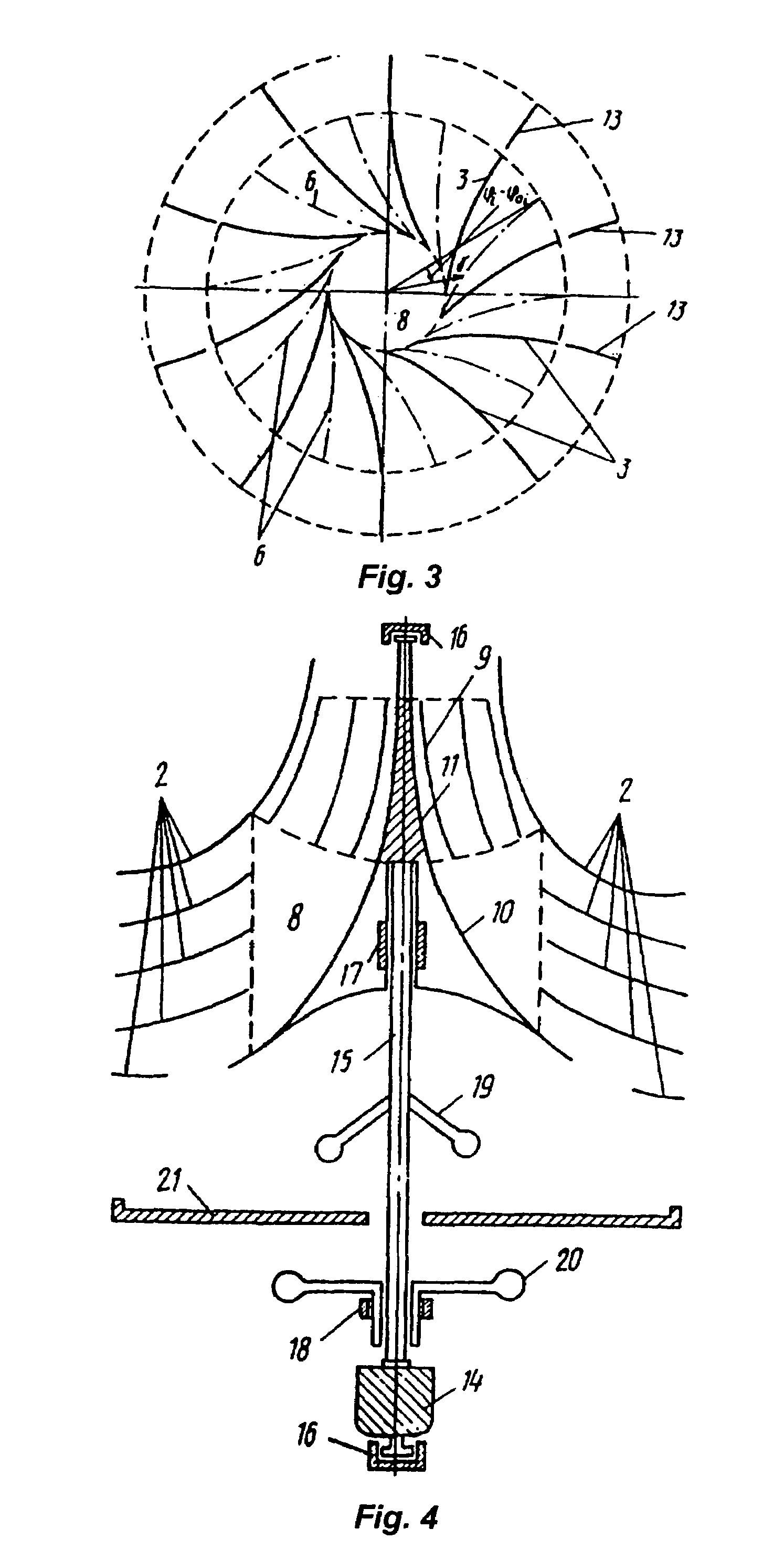
[0104]The proposed method of conversion of the energy of a turbulent continuous medium flow is realised, as indicated in FIG. 1, in the following way:

[0105]The formed flow is directed along the two systems of radially converging confuser trajectories into the internal axissymmetric volume; the first system of trajectories A-A1, B-B1, A′-A′1 and B′-B′1 fills at first the space area limited by the two surfaces of revolution T1 and T2, whereas the second system of trajectories C-C1, D-D1, C′-C′1 and D′-D′1 is formed as a result of the interaction between the directed flow and the concave surface of revolution T3.

[0106]In the course of the flow motion the first system of trajectories is shaped as helical trajectories E-E1, F-F1, E′-E′1 and F-F′1; as the formed flow passes through this system, a vortex flow is generated from part of this flow just in front of the zone of conversion of the rotational moment and mechanical energy K, which are concentrated in the said flow due to merging of...


PUM


Abstract

A device and method for conversion of the energy of medium flows are provided. The proposed device and method ensure suppression of the vortex streams in the flow on the leg of its motion along the radially converging trajectories and concentration of the flow energy, which is expressed by the increase of its velocity and decrease of the summary area of the cross section of the converging trajectories. As the flow runs along the first system of helical trajectories the following takes place: the harmful secondary vortex jets continue attenuating, the degree of concentration of the flow energy increases and velocity components form in the flow, which correspond to natural vortex streams, for instance, tornadoes, whirlpools. The formation of a vortex as the flow runs along the first system of trajectories results in a concentrated steady vortex flow with an effective concentration of the pressure differential into kinetic energy of the motion of particles and into a rotational moment, which are required for complete transfer of the energy to the rotational moment and energy receiver.

Description

BACKGROUND OF THE INVENTION[0001]1. Field of the Invention[0002]The invention relates to power engineering and, in particular, to the methods and devices for conversion of the continuous medium flow energy into mechanical energy.[0003]This invention may be used in wind and hydraulic driven power engineering in various hydraulic and gas dynamic systems, for instance, when the motion of liquids, gas, two-phase or multicomponent media is used for mechanical energy generation.[0004]The invention can be most successfully used in wind-driven electric power plants, in hydroelectric power plants, arranged in river beds (without dams), in tide-driven hydroelectric power plants, as well as when the energy of thermoinduced flows is utilised including sun-heated thermoinduced flows.[0005]2. Description of Related Art[0006]Known are methods of concentration of the wind flow power by placing into the flow devices in the form of a convergent-divergent reflector arranged coaxially with the directio...

Claims


Application Information

Patent Timeline
IPC IPC(8): F03B3/18F03D3/04F03B1/00F03D1/04
CPCF03D1/04F05B2210/16F05B2240/122F05B2240/132Y02E10/72Y10S415/914Y10S415/909F03D9/007F03D9/39F03D15/20Y02E10/728Y10T137/2093
Inventor KIKNADZE, GENNADY IRAKLIEVICHGACHECHILADZE, IVAN ALEXANDROVICH
Owner INVENTORS NETWORK
Learn More