
A catalytic conversion method for increasing production of gasoline and low-carbon olefins

A catalytic conversion method and technology for low-carbon olefins, which are applied in the directions of catalytic cracking, cracking, and processing of hydrocarbon oil, can solve problems such as difficult implementation, low gasoline yield, and complex process, and achieve uniform contact, prolonged reaction time, Strengthen the effect of efficient conversion

Active Publication Date: 2021-01-01
PETROCHINA CO LTD
View PDF8 Cites 0 Cited by
  • Summary
  • Abstract
  • Description
  • Claims
  • Application Information

AI Technical Summary

Problems solved by technology

The patent uses two riser reactors, the embedded riser uses mixed C4, FCC light gasoline, light naphtha, and light diesel oil as raw materials, and the outer embedded riser uses Daqing mixed oil or Daqing vacuum residue as raw materials , the gasoline yield is low, and the process is relatively complicated, making it difficult to implement

Method used


Image

  • A catalytic conversion method for increasing production of gasoline and low-carbon olefins
  • A catalytic conversion method for increasing production of gasoline and low-carbon olefins
  • A catalytic conversion method for increasing production of gasoline and low-carbon olefins

Examples


Embodiment 1

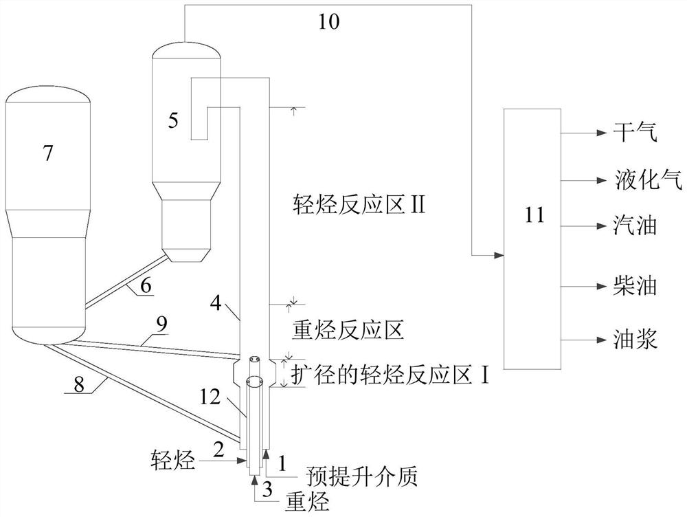
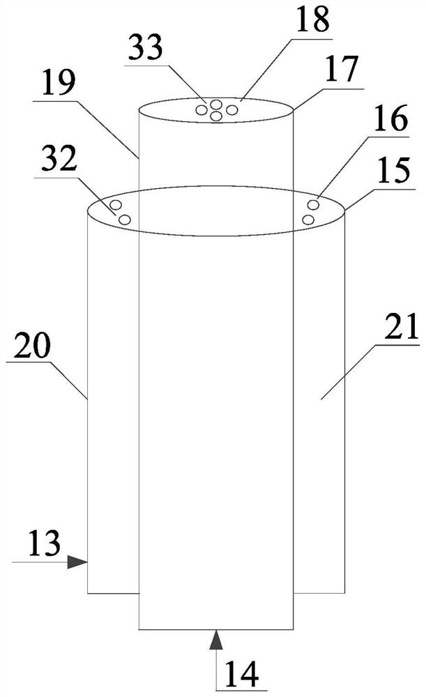
[0047] use figure 1 The device shown and figure 2 The one-piece nozzle shown was tested.

[0048] The heights of the expanded light hydrocarbon reaction zone I, heavy hydrocarbon reaction zone and light hydrocarbon reaction zone II account for 5%, 35% and 55% of the total height of the riser reactor respectively. The ratio of the inner diameter of the riser reactor in the enlarged light hydrocarbon reaction zone I to the inner diameter of the riser reactor in the heavy hydrocarbon reaction zone is 1.5:1. The ratio of the outer diameter of the light hydrocarbon casing 20 of the integrated nozzle 12 to the outer diameter of the heavy hydrocarbon outer casing 19 is 2.20:1, and the diameter of a single light hydrocarbon injection hole on the light hydrocarbon nozzle 16 is the same as that of the single heavy hydrocarbon nozzle 18 on the heavy hydrocarbon outer nozzle. The aperture ratio of the hydrocarbon outer injection holes is 1.429:1. The pre-lift medium was nitrogen.

[...

Embodiment 2

[0056] use figure 1 The device shown and figure 2 The one-piece nozzle shown was tested.

[0057] The heights of the expanded light hydrocarbon reaction zone I, heavy hydrocarbon reaction zone and light hydrocarbon reaction zone II account for 5%, 35% and 55% of the total height of the riser reactor respectively. The ratio of the inner diameter of the riser reactor in the enlarged light hydrocarbon reaction zone I to the inner diameter of the riser reactor in the heavy hydrocarbon reaction zone is 1.5:1. The ratio of the outer diameter of the light hydrocarbon casing 20 of the integrated nozzle 12 to the outer diameter of the heavy hydrocarbon outer casing 19 is 2.20:1, and the diameter of a single light hydrocarbon injection hole on the light hydrocarbon nozzle 16 is the same as that of the single heavy hydrocarbon nozzle 18 on the heavy hydrocarbon outer nozzle. The aperture ratio of the hydrocarbon outer injection holes is 1.429:1. The pre-lift medium was nitrogen.

[...

Embodiment 3

[0066] use figure 1 The device shown and figure 2 The one-piece nozzle shown was tested.

[0067] The heights of the expanded light hydrocarbon reaction zone I, heavy hydrocarbon reaction zone and light hydrocarbon reaction zone II account for 5%, 35% and 55% of the total height of the riser reactor respectively. The ratio of the inner diameter of the riser reactor in the enlarged light hydrocarbon reaction zone I to the inner diameter of the riser reactor in the heavy hydrocarbon reaction zone is 1.5:1. The ratio of the outer diameter of the light hydrocarbon casing 20 of the integrated nozzle 12 to the outer diameter of the heavy hydrocarbon outer casing 19 is 2.20:1, and the diameter of a single light hydrocarbon injection hole on the light hydrocarbon nozzle 16 is the same as that of the single heavy hydrocarbon nozzle 18 on the heavy hydrocarbon outer nozzle. The aperture ratio of the hydrocarbon outer injection holes is 1.429:1. The pre-lift medium was nitrogen.

[...


PUM

PropertyMeasurementUnit
boiling pointaaaaaaaaaa

Abstract

The invention relates to a catalytic conversion method for increasing the yield of gasoline and low-carbon olefins. The invention mainly solves the problems of low gasoline yield and complicated process in a conventional catalytic cracking process or a catalytic cracking coupled hydrogenation process. The catalytic conversion method provided by the invention comprises the following steps: introducing two regenerant delivery pipes from a regenerator to respectively deliver a regenerated catalyst to a diameter-expanded light hydrocarbon reaction zone I and a heavy hydrocarbon reaction zone in the reaction zone of a lift pipe reactor, and allowing preheated light hydrocarbons and heavy hydrocarbons to be simultaneously and respectively sprayed into the light hydrocarbon reaction zone I and the heavy hydrocarbon reaction zone from an integrated spray nozzle to contact, react and move upward with a high-temperature regenerated catalyst from the regenerator; and allowing a reaction product and a carbon deposit-containing catalyst to flow out of the reactor from the outlet of the top part of the reactor and to enter a cyclone separation system for separation, and allowing a separated reaction product to enter a fractionating tower through an oil and gas pipeline for fractional distillation so as to obtain a corresponding product. The catalytic conversion method provided by the invention has the characteristic of increasing the yield of the gasoline and the low-carbon olefins.

Description

technical field [0001] The invention relates to a method for catalytic conversion of petroleum hydrocarbons, more specifically, to a method for catalytic conversion of heavy diesel oil and low-quality heavy oil to increase the production of gasoline and low-carbon olefins in the absence of hydrogen. Background technique [0002] Under the new economic normal, the consumption of China's major refined oil products is still on the rise. The rigid demand for gasoline is growing rapidly, while the growth rate of diesel demand is greatly reduced. Before 2020, the growth rate of my country's gasoline demand will be faster than that of diesel. The demand for low-carbon olefins such as propylene and butadiene is increasing. Due to the heavy weight of crude oil in my country, the yield of naphtha fractions with a boiling point less than 200°C is low, which can only provide less than 50% of steam cracking raw materials for the production of low-carbon olefins. As one of the main means ...

Claims


Application Information

Patent Timeline
Patent Type & Authority Patents(China)
IPC IPC(8): C10G57/00C10G11/14C10G11/18
CPCC10G11/14C10G11/182C10G57/00C10G2300/1055C10G2300/1092C10G2400/02C10G2400/20
Inventor 侯凯军王智峰高永福高雄厚李荻张海涛王宝杰刘从华孟凡芳石晓庆王莉
Owner PETROCHINA CO LTD
Learn More