Leak detector of liquid in tank

a leak detector and tank technology, applied in fluid tightness measurement, instruments, machines/engines, etc., can solve the problems of increasing the error in the flow rate measurement value, the leakage of liquid in the tank from the tank, and the cracks of the tank, so as to reduce power consumption, improve accuracy, and accurately detect the effect of minute leakag

Active Publication Date: 2008-02-26
SAN-A
View PDF27 Cites 12 Cited by
  • Summary
  • Abstract
  • Description
  • Claims
  • Application Information

AI Technical Summary

Benefits of technology

[0056]In the present invention, the difference between the output of the leak detecting circuit and its initial value is integrated in response to the application of the single pulse voltage to the heater which is performed by the pulse voltage generating circuit to calculate the value equivalent to the flow rate of the liquid in the measuring slim-tube to thereby detect leakage of the liquid in the tank based on the calculated value. With this configuration, it is possible to perform leakage detection over a long period of time without stopping the use of the tank and reduce power consumption. Therefore, it is possible to use a battery installed in the structural section of the leak detector as a power source for the heater as well as to perform leakage detection over a long period of time without requiring battery replacement.
[0057]Further, in the present invention, the first leakage detection and the second leakage detection are performed. The first leakage detection uses the first temperature sensor, the heater and the second temperature sensor which are arranged this order along the measuring slim-tube and allows the heater to generate heat to detect leakage of the liquid in the tank based on the value equivalent to the liquid flow rate which is calculated by using the leak detecting circuit output corresponding to the difference between temperatures detected by the first and second temperature sensors. The second leakage detection detects leakage of the liquid in the tank based on the magnitude of the variation rate with respect to time of the liquid level which is measured by the pressure sensor. In the case where the magnitude of the liquid level variation rate with respect to time falls within the predetermined range in the second leakage detection, the result of the second leakage detection is output. In the case where the magnitude of the liquid level variation rate with respect to time falls below the lower limit of the predetermined range in the second leakage detection, the result of the first leakage detection is output. In the case where the magnitude of the liquid level variation rate with respect to time falls above the upper limit of the predetermined range in the second leakage detection, the output of the leakage detection signal is stopped. With the above configuration, it is possible to accurately detect minute leakage, excluding an abrupt liquid level variation occurring when liquid is introduced into the tank from the outside or when liquid is supplied to the outside. Further, it is possible to detect leakage over a necessary and sufficient leakage amount range with higher accuracy.
[0058]When the pulse voltage generating circuit is used as the voltage generating circuit, the difference between the output of the leak detecting circuit and its initial value is integrated in response to the application of the single pulse voltage to the heater which is performed by the pulse voltage generating circuit to calculate the value equivalent to the flow rate of the liquid in the measuring slim-tube to thereby detect leakage of the liquid in the tank based on the calculated value. With this configuration, it is possible to perform leakage detection over a long period of time without stopping the use of the tank and reduce power consumption. Therefore, it is possible to use a battery installed in the structural section of the leak detector as a power source for the heater as well as to perform leakage detection over a long period of time without requiring battery replacement.
[0059]Further, in the present invention, the first temperature sensor, the heater and the second temperature sensor are arranged in this order along the measuring slim-tube and the heater is allowed to generate heat. The leak detecting circuit generates the output corresponding to the difference between temperatures detected by the first and second temperature sensors. The leak detecting circuit is used to detect the specific gravity of the liquid in the tank based on the value equivalent to the liquid flow rate which is calculated by using the output of the leak detecting circuit in the state where the on-off valve provided in the upper portion of the measuring tube connected to the upper end of the measuring slim-tube and having the sectional area larger than that thereof is closed. The specific gravity value obtained in the above detection is used to measure the liquid level by means of the pressure sensor to thereby detect leakage of the liquid in the tank based on the magnitude of the liquid level variation rate with respect to time. With the above configuration, it is possible to increase accuracy in detecting leakage of the liquid in the tank based on the variation of the liquid level measured by the pressure sensor irrespective of a value of the specific gravity of the liquid in the tank.
[0060]Further, in the present invention, the minute leakage detection detects leakage of the liquid in the tank based on the value equivalent to the liquid flow rate which is calculated by using the output of the leak detecting circuit in the state where the on-off valve is opened, and the leakage detection detects leakage of the liquid in the tank based on the magnitude of the variation rate with respect to time of the liquid level which is measured by the pressure sensor. In the case where the magnitude of the liquid level variation rate with respect to time falls within the predetermined range in the leakage detection, the result of the leakage detection is output. In the case where the magnitude of the liquid level variation rate with respect to time falls below the lower limit of the predetermined range in the leakage detection, the result of the minute leakage detection is output. In the case where the magnitude of the liquid level variation rate with respect to time falls above the upper limit of the predetermined range in the leakage detection, the output of the leakage detection signal is stopped. With the above configuration, it is possible to accurately detect minute leakage, excluding an abrupt liquid level variation occurring when liquid is introduced into the tank from the outside or when liquid is supplied to the outside. Further, it is possible to detect leakage over a necessary and sufficient leakage amount range with higher accuracy.
[0061]When the pulse voltage generating circuit is used as the voltage generating circuit, the difference between the output of the leak detecting circuit and its initial value is integrated in response to the application of the single pulse voltage to the heater which is performed by the pulse voltage generating circuit to calculate the value equivalent to the flow rate of the liquid in the measuring slim-tube to thereby detect leakage of the liquid in the tank based on the calculated value. With this configuration, it is possible to perform leakage detection over a long period of time without stopping the use of the tank and reduce power consumption. Therefore, it is possible to use a battery installed in the structural section of the leak detector as a power source for the heater as well as to perform leakage detection over a long period of time without requiring battery replacement.

Problems solved by technology

The tank may suffer some cracks due to time degradation.
In this case, liquid in the tank leaks from the tank.
However, in the indirectly heated flowmeter used in the liquid leakage detection device disclosed in the above Patent Document 1, a variation in an electric circuit output level with respect to a variation in a liquid flow rate becomes small in the region where the flow rate value is as infinitesimal as, e.g., 1 milliliter / h or less, so that an error in the flow rate measurement value tends to increase.
Thus, there is a limit to an improvement in leakage detection accuracy.
There is a possibility that an electrical leakage may occur in such a power wire particularly at the lead-in portion to the structural section of the liquid leakage detection device over a long-term use.
In the case where a flammable liquid or an electrically conductive liquid is used, a fire or short-circuit associated with the electrical leakage may be caused on the liquid adhered to the structural section of the liquid leakage detection device in some cases.
Therefore, when leakage detection is performed for, e.g., kerosene contained in a tank, even if a specific gravity value of standard kerosene is input, as a specific gravity of liquid, to the conversion program from a liquid pressure to liquid level, an error occurs in the conversion when the kerosene actually contained in a tank has a different specific gravity value from the standard kerosene.
Thus, in the case where leakage detection is performed for the mixed composition such as kerosene, liquid level measurement includes the above conversion error, resulting in a reduction of accuracy in leakage detection.

Method used


Image

  • Leak detector of liquid in tank
  • Leak detector of liquid in tank
  • Leak detector of liquid in tank

Examples


Embodiment Construction

[0078]Embodiment of the present invention will be described below with reference to the accompanying drawings.

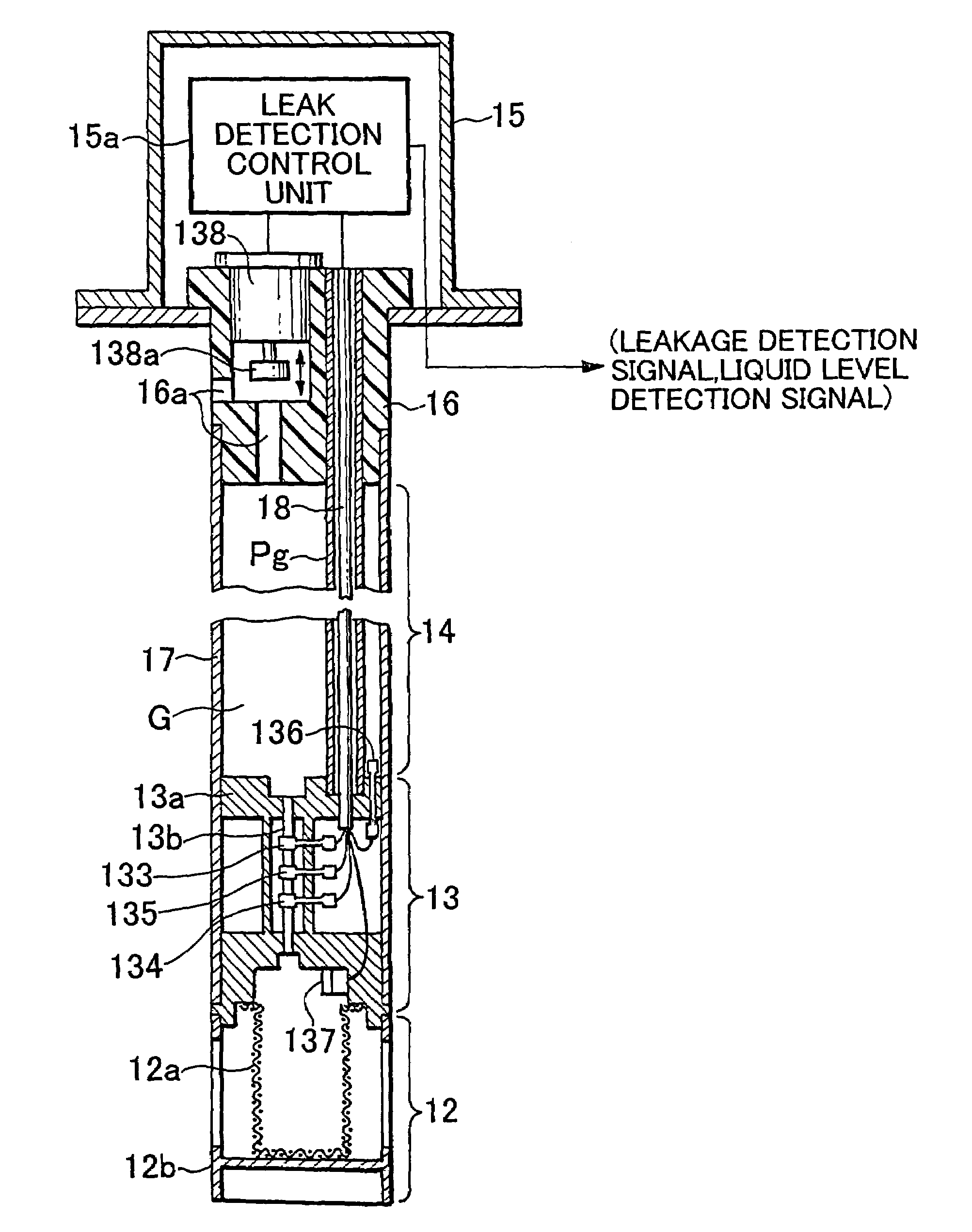
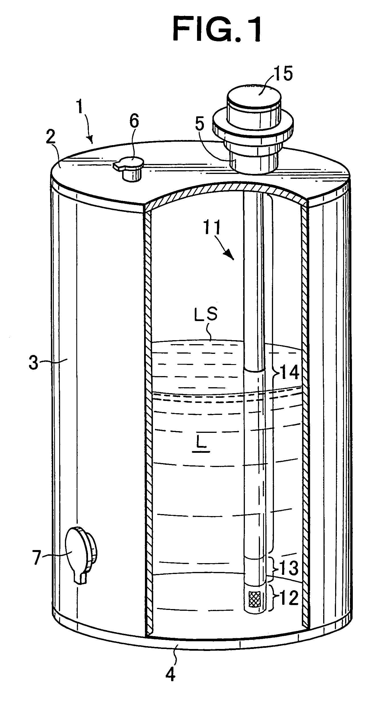
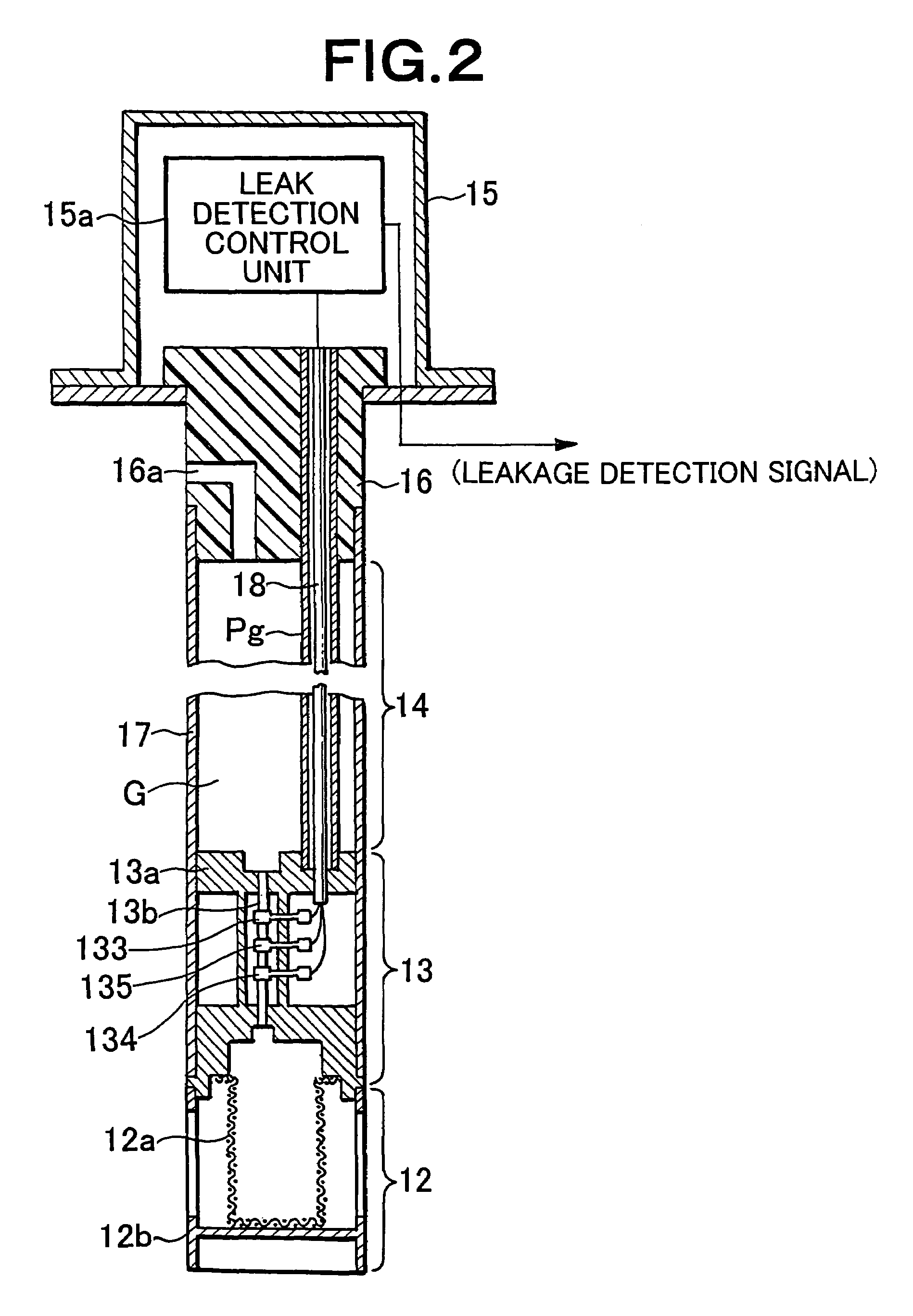
[0079]FIG. 1 is a partially broken view for explaining an embodiment of a leak detector of liquid in a tank according to the present invention, and FIG. 2 is a partially omitted cross-sectional view of the leak detector according to the present embodiment.

[0080]A tank 1 has a top panel 2 in which a measurement port 5 and a liquid inlet 6 used when liquid is introduced into the tank are formed, a side panel 3 in which a liquid supply port 7 used when liquid in the tank is supplied to the outside is formed, and a bottom panel 4. As shown in FIG. 1, liquid L (flammable liquid of mixed composition containing many organic compounds such as gasoline, diesel oil, kerosene, or the like) is contained in the tank 1. LS denotes a liquid surface.

[0081]A portion of a leak detector 11 is inserted into the tank 1 through the measurement port 5 formed in the top panel 2 of the tank 1, and t...


PUM


Abstract

A leak detector comprising a sensor unit including a measuring slim-tube (13b) via the lower end of which a liquid in a tank is led in / out, a measuring tube (17) connected to the upper end thereof and having a sectional area larger than that thereof, and temperature sensors (133, 134) and a heater (135) provided to the slim-tube (13b), and a leak detection control unit (15a) connected to the sensor unit. The leak detection control unit (15a) has a pulse voltage generating circuit for applying a single pulse voltage to the heater (135) and a leak detecting circuit that is connected to the temperature sensors (133, 134) and produces an output equivalent to a temperature difference sensed by these temperature sensors, whereby a value equivalent to a liquid flow rate is calculated by integrating the difference between an output from the leak detecting circuit and its initial value according to a single pulse voltage applied to the heater (135) by the pulse voltage generating circuit, and leakage of liquid from the tank is detected based on this value.

Description

[0001]This application is a 371 of PCT / JP2004 / 012479 filed on Aug. 30, 2004, published on May 12, 2005 under publication number WO 2005 / 043104 A1 which claims priority benefits from Japanese Patent Application Number 2003-372766 filed Oct. 31, 2003, Japanese Patent Application Number 2003-372767 filed Oct. 31, 2003, Japanese Patent Application Number 2003-372768 filed Oct. 31, 2003 and Japanese Patent Application Number 2004-223687 filed Jul. 30, 2004.TECHNICAL FIELD[0002]The present invention relates to a leak detector of liquid in a tank and, more particularly to, a detector of leak of liquid from a tank by converting it into a flow based on the level variation of liquid in a tank.BACKGROUND ART[0003]Fuel oil or various liquid chemicals are stored in a tank. In recent years, for example, a centralized oiling system for collective housing has been proposed. In this system, kerosene is supplied to the respective homes from a centralized kerosene tank through tubes.[0004]The tank may...

Claims


Application Information

Patent Timeline
Patent Type & Authority Patents(United States)
IPC IPC(8): G01M3/04G01M3/00G01M3/26G01M3/32
CPCG01M3/002G01M3/3245G01M3/3254
Inventor YANAGI, KIYOTAKAKOIKE, ATSUSHINAKAMURA, TOSHIMIYAMAGISHI, KIYOSHISEKIMORI, HIDESHI
Owner SAN-A
Why Eureka
Try Eureka