Method of correcting color image data according to correction table

a color image data and correction table technology, applied in the field of image processing method for correcting color image data, can solve the problem of slightly increasing the total processing time, and achieve the effect of reducing the pre-conversion error and high-speed output of high-quality image data

Active Publication Date: 2008-02-26
SEIKO EPSON CORP
View PDF28 Cites 18 Cited by
  • Summary
  • Abstract
  • Description
  • Claims
  • Application Information

AI Technical Summary

Benefits of technology

[0074]The computer reads the computer program stored in the computer program product and executes the respective functions discussed above to reduce the pre-conversion error arising in the process of correcting the color image data, thus ensuring high-speed output of high-quality image data.

Problems solved by technology

An increase in number of lattice points to be referred to thus results in only slightly increasing the total processing time.

Method used


Image

  • Method of correcting color image data according to correction table
  • Method of correcting color image data according to correction table
  • Method of correcting color image data according to correction table

Examples


first embodiment

C. First Embodiment

C-1. Construction of System

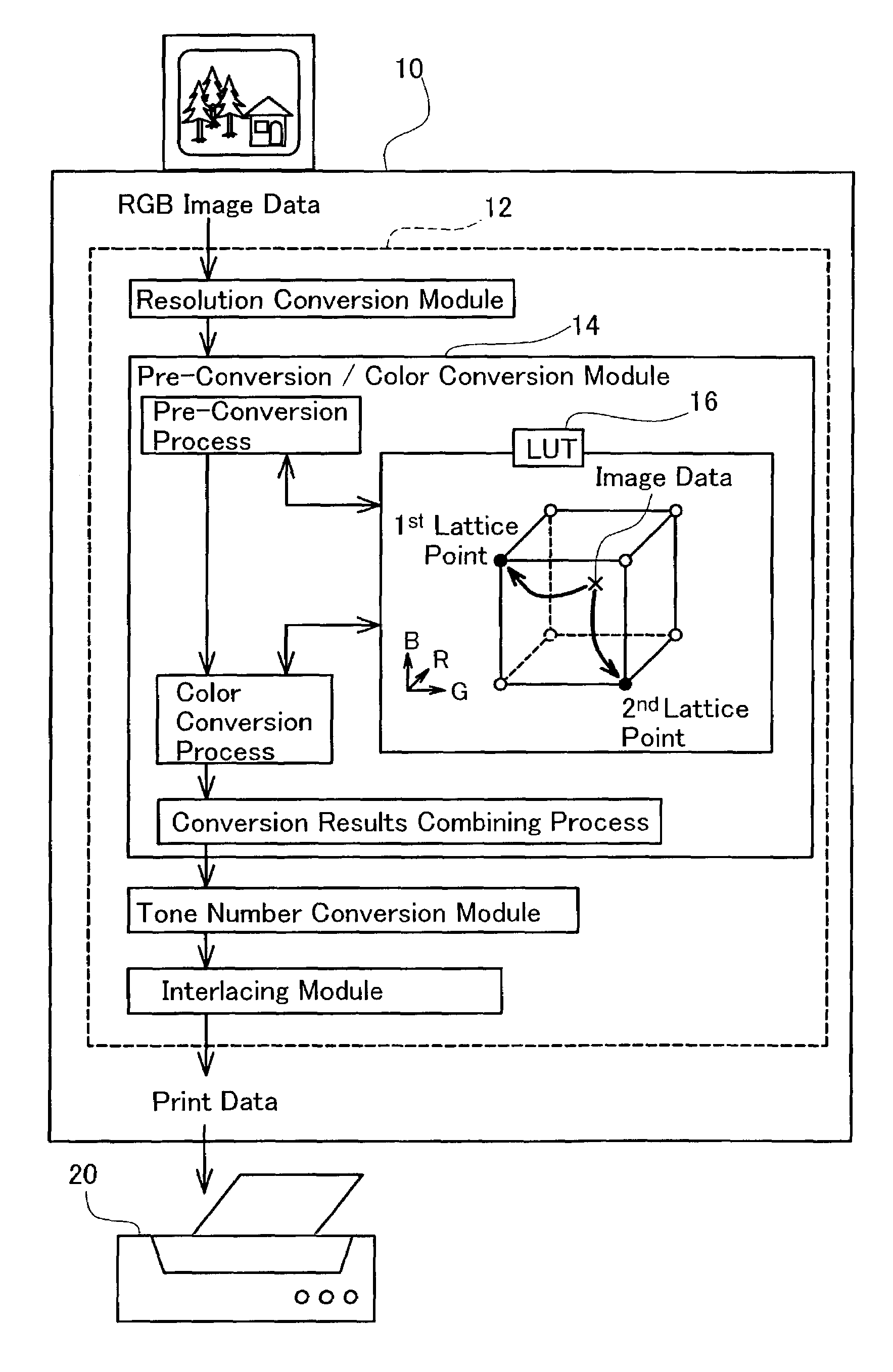
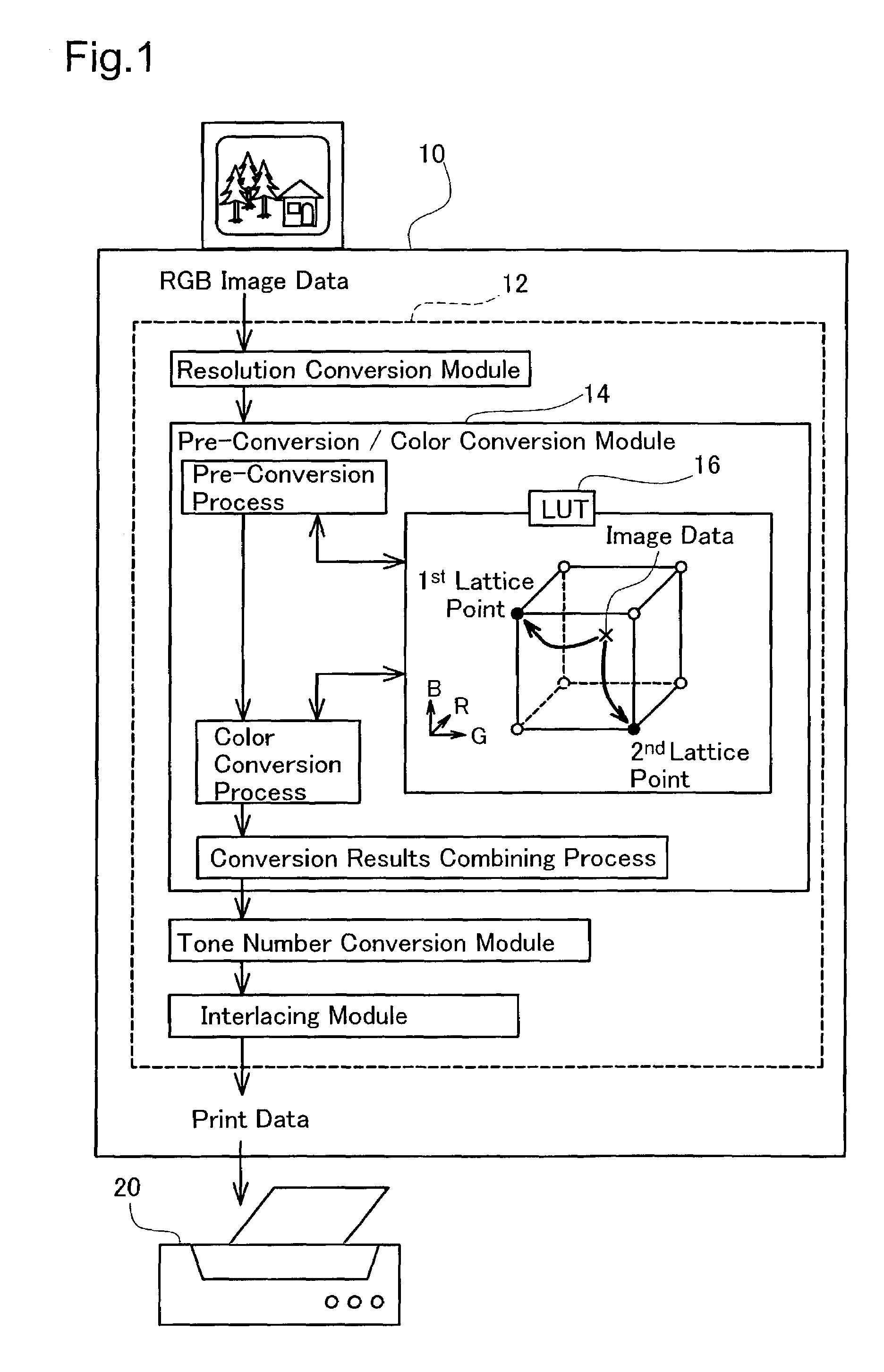
[0169]FIG. 6 schematically illustrates the construction of a computer 100 as an image processing apparatus of a first embodiment according to the present invention. The computer 100 corresponds to the computer 10 shown in FIG. 1 and is constructed as a known computer including a CPU 102, a ROM 104, and a RAM 106, which are mutually connected via a bus 116.

[0170]The computer 100 also includes a disk controller DDC 109 for reading data from a flexible disk 124 or a compact disc 126, a peripheral equipment interface P / IF 112 for transmission of data to and from peripheral equipment, and a video interface V / IF 112 for actuating a CRT 114. A color printer 200 (discussed later), which corresponds to the color printer 20 shown in FIG. 1, and a hard disk 118 are linked with the P / IF 108. Connection of a digital camera 120 or a color scanner 122 to the P / IF 108 enables images transmitted from the digital camera 120 and those read by the color sca...

second embodiment

D. Second Embodiment

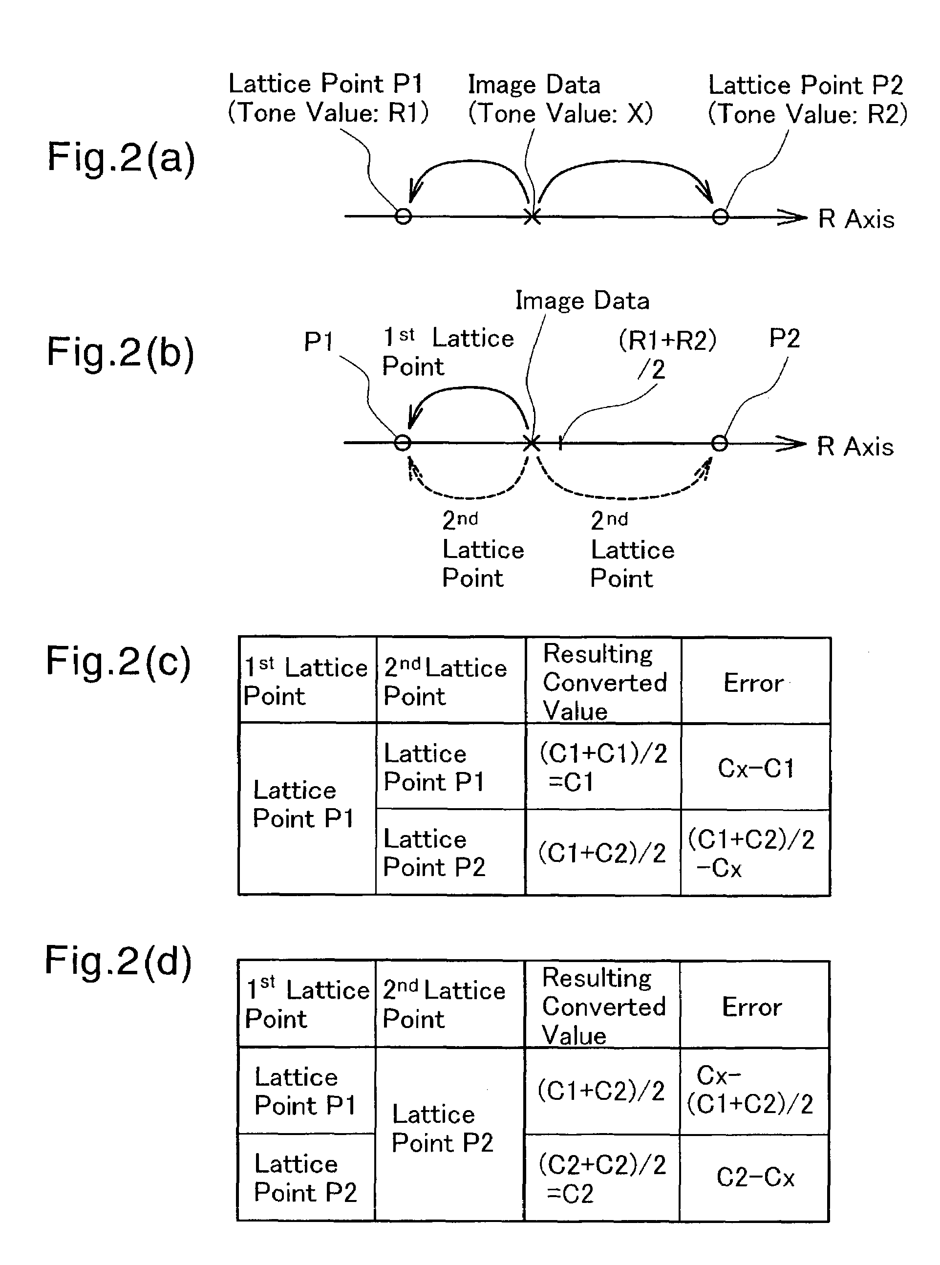
[0244]The procedure of the first embodiment allocates the image data Dx to the two lattice points, the first lattice point and the second lattice point. The number of lattice points, to which the image data Dx is allocated, is not restricted to 2, but may be greater than 2. The following describes such a case as a pre-conversion / color conversion procedure of a second embodiment.

D-1. Pre-Conversion Process of Second Embodiment

[0245]FIG. 23 is a flowchart showing a processing routine of allocating image data to multiple lattice points (pre-conversion process) carried out in the second embodiment. This process is executed after the step of reading image data in the pre-conversion / color conversion process shown in the flowchart of FIG. 10. The primary difference from the pre-conversion process of the first embodiment discussed previously with reference to the flowchart of FIG. 11 is an increase in number of the lattice points, to which the image data is allocated, to...

third embodiment

E. Third Embodiment

[0271]In the first and the second embodiments discussed above, N noises are used for allocation of the image data to N lattice points. For example, the procedure of the first embodiment uses the first noise Ns1 for setting the first lattice point and the second noise Ns2 for setting the second lattice point. The number of noises may, however, be different from the number of lattice points, to which the image data is allocated. Only one noise may be used for allocation of the image data to multiple lattice points. This application is discussed below as a pre-conversion process of a third embodiment.

E-1. Pre-Conversion Process of Third Embodiment

[0272]FIG. 30 is a flowchart showing a processing routine of the pre-conversion process carried out in the third embodiment.

[0273]When the program enters the pre-conversion process of the third embodiment, the printer driver 12 first detects the coordinate values of each lattice point in the vicinity of target image data Dx ...


PUM

PropertyMeasurementUnit
processingaaaaaaaaaa
color imageaaaaaaaaaa
lattice pointsaaaaaaaaaa

Abstract

The technique of the present invention allocates a coordinate point of target image data on a color space to multiple lattice points in a color conversion table and reads data stored at the multiple lattice points. This arrangement ensures high-speed color conversion of the target image data. The procedure selects multiple lattice points and allocates a coordinate point of one target image data to the selected multiple lattice points. The procedure then specifies color-converted image data corresponding to the target image data, based on data read from the multiple lattice points. A first application allocates the target image data to the coordinate points of the multiple lattice points arbitrarily selected in the vicinity of the target image data. A second application allocates N-dimensional target image data to the coordinate points of multiple but not greater than N lattice points. A third application calculates an arithmetic mean of the data read from the multiple lattice points to specify the color-converted image data. Any of these arrangement effectively enhances the conversion accuracy without increasing the size of the color conversion table.

Description

BACKGROUND OF THE INVENTION[0001]1. Field of the Invention[0002]The present invention relates to an image processing method for correcting color image data. More specifically the invention pertains to a technique of quick image processing by referring to a correction table.[0003]2. Description of the Related Art[0004]A known image processing apparatus reads a color original with an image input unit, such as a scanner, to input color image data and reproduces the input color image data with an image output unit, such as a CRT, another display, or a color printer.[0005]Each of the image output units like displays and color printers has intrinsic color reproduction properties. Color correction according to the color reproduction properties of each image output unit is accordingly required for favorable reproduction of the colors of a color image input with a scanner or another image input unit, regardless of the properties of the image output unit. A typical technique of color correcti...

Claims


Application Information

Patent Timeline
Patent Type & Authority Patents(United States)
IPC IPC(8): G06F15/00G03F3/08G06T1/00H04N1/46H04N1/60
CPCH04N1/6019
Inventor KAKUTANI, TOSHIAKI
Owner SEIKO EPSON CORP
Why Eureka
Try Eureka