
Optical encoding and reconstruction

a technology applied in the field of optical encoding and reconstruction, can solve the problems of difficult manufacturing, lower resolution, and difficult separation of one column from the other

Active Publication Date: 2008-03-04
DELIWALA SHRENIK
View PDF13 Cites 39 Cited by
  • Summary
  • Abstract
  • Description
  • Claims
  • Application Information

AI Technical Summary

Benefits of technology

This approach reduces manufacturing complexity and cost by using a single detector, improves resolution through software determination, and allows imaging across various electromagnetic spectra without the need for exotic materials, while maintaining a high signal-to-noise ratio.

Problems solved by technology

Taller the pixel column, lower the resolution for a given acceptance angle for X-rays and harder it is to isolated one column from the other.
For example, metal coated or air isolated scintillator columns have been used to reduce X-ray and optical crosstalk but are difficult to manufacture.
In order to satisfy the need for high-resolution, high-efficiency imaging, thinner scintillator materials with high stopping power such as CsI are used which are often expensive compared to NaI or many organic scintillators.
Traditional imaging detectors have difficulty maintaining the trade-offs mentioned above as higher energy X-rays need thicker scintillators.
Most of the above regions of electromagnetic spectrum use expensive detector technologies and the imaging arrays may be particularly expensive.
This may further reduce the cost of the imaging systems where lens materials are expensive and / or difficult to fabricate.
Ellipsometry in the UV region may become difficult due to the poor responsivity of Silicon detectors in the UV and higher transmission losses of UV light resulting in small signals.
Multiple spatial fringes (due to tilted beams) within the size of the image on the detector will tend to wash out the interference term.
Also, the overlap of the upper sideband with the direct terms further complicates the matter.
This reduces the actual resolution of the CCD and causes well known issues of color Moire patterns as well loss of color fidelity.
Generally, making the image field flat in order to produce a sharp image on a planar imaging surface increases the complexity of the imaging system and adds to the cost of optics.
It is quite difficult to acquire high-resolution images of the retina using a standard planar imaging system since the human lens in the eye is designed to image on a curved surface—the surface of the retina.
In many imaging applications, lenses are either expensive or nonexistent.
In this case, the size of the detector limits the resolution of the reconstructed image.

Method used


Image

  • Optical encoding and reconstruction
  • Optical encoding and reconstruction
  • Optical encoding and reconstruction

Examples


Embodiment Construction

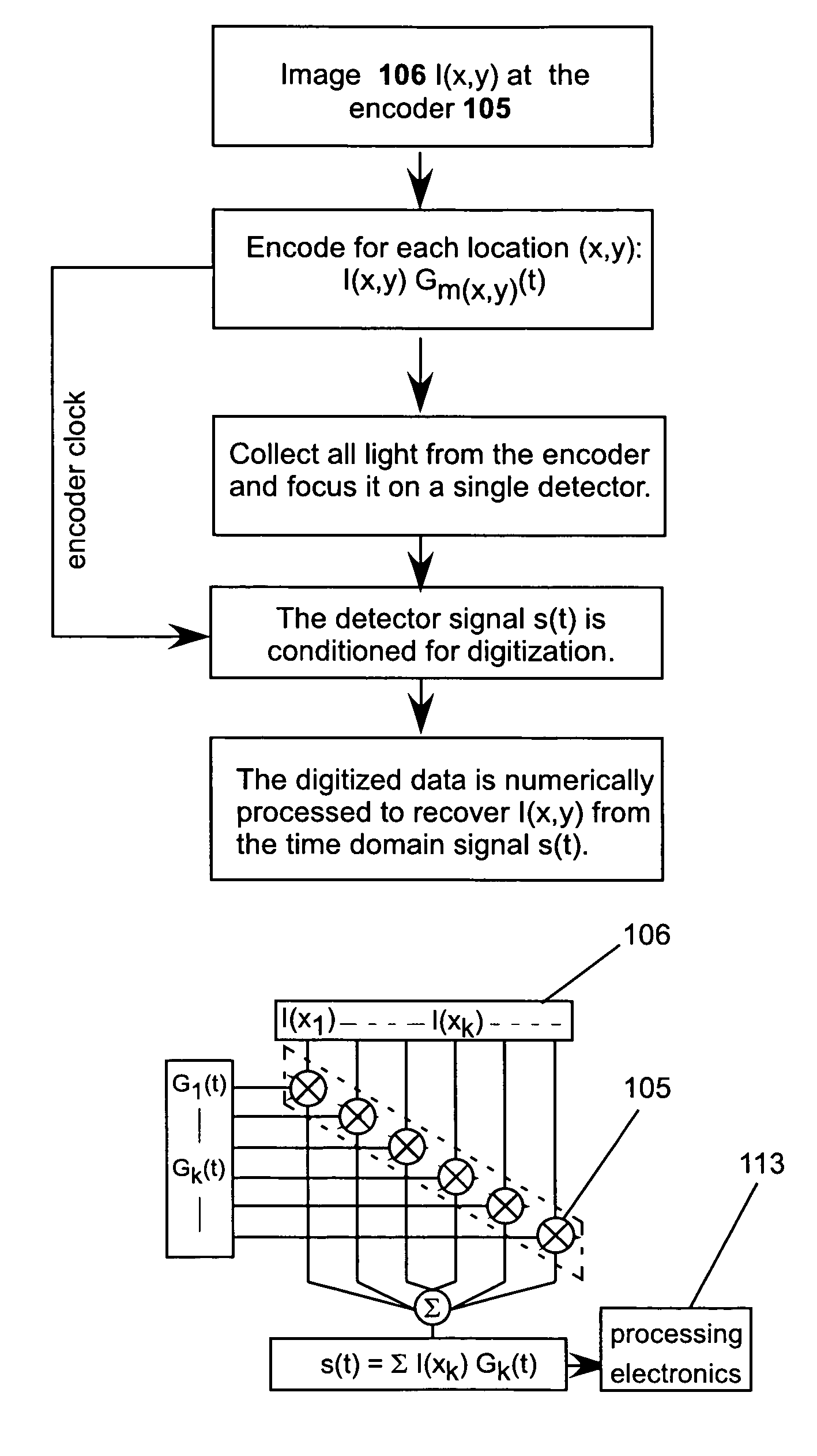
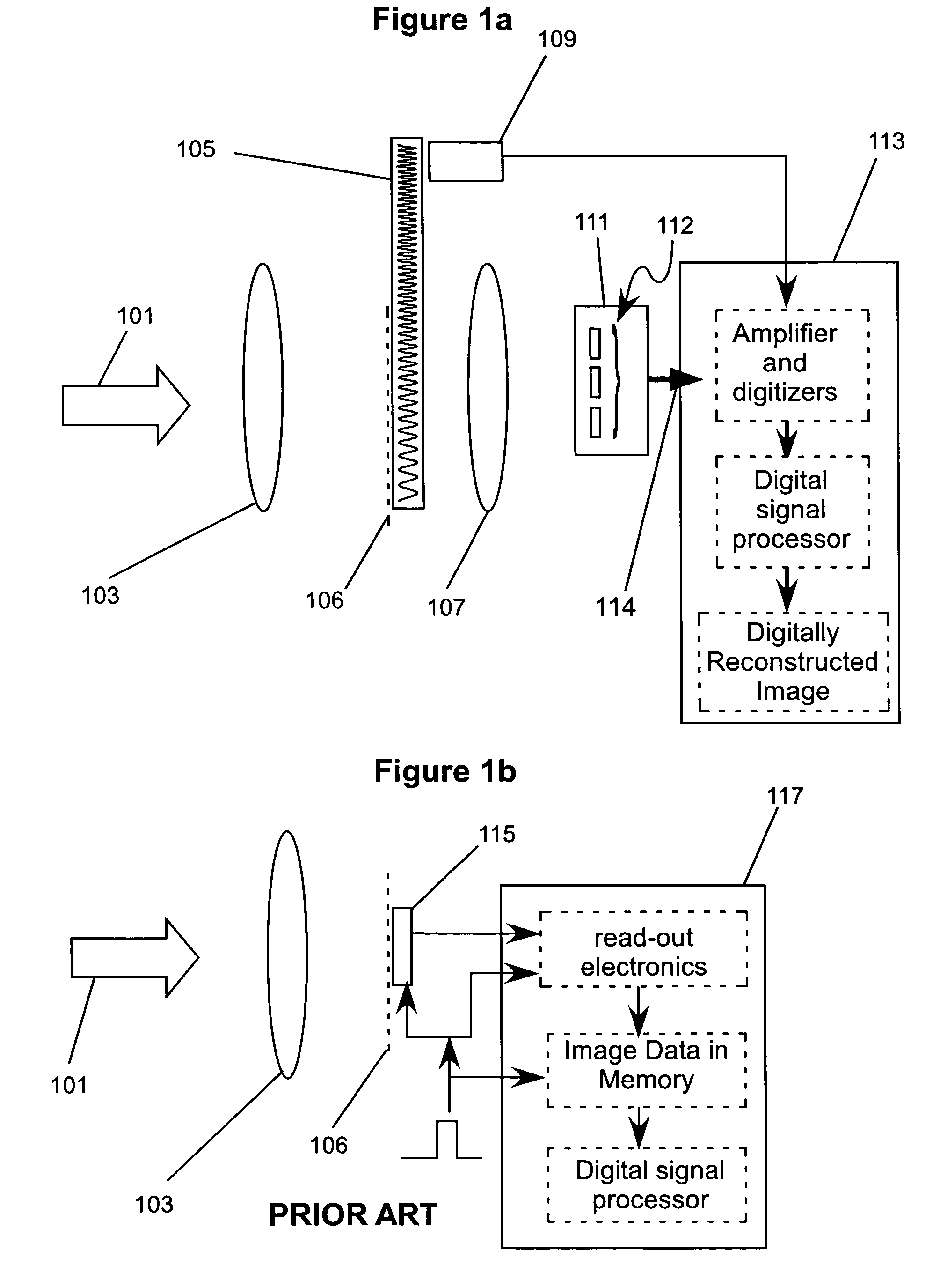
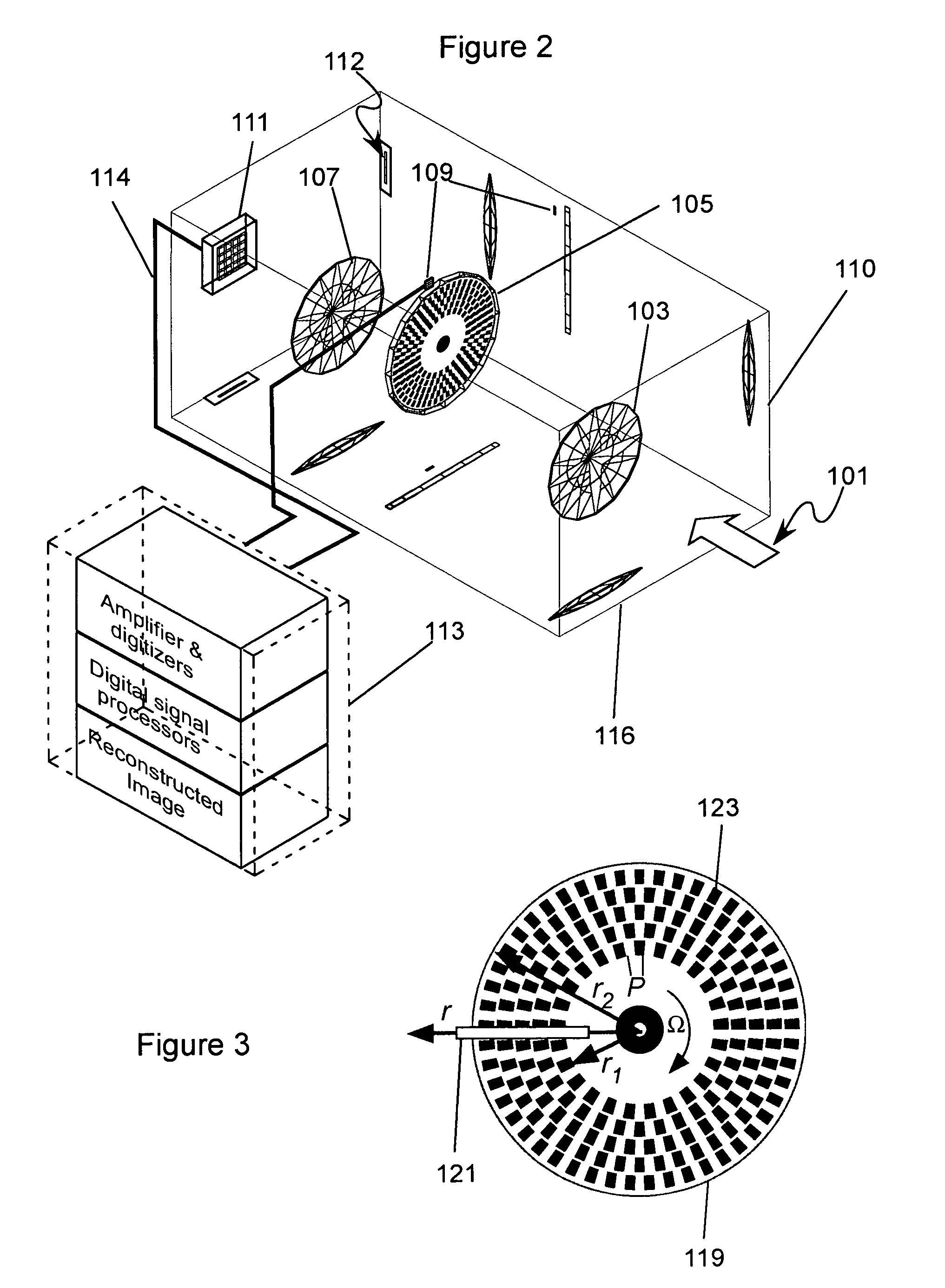
[0093]This invention relates to a technique of encoding a one or two dimensional spatial information, collection, and its computational reconstruction. The disclosed methods may be applied to the problem of imaging electromagnetic radiation, spectroscopy, and other methods that usually require a one or two dimensional pixelated array of detectors. The disclosed method enables new imaging modes such as ranging to be combined with a standard one or two-dimensional image. These novel capabilities are accomplished by a special set of methods for dynamic encoding of the image information. This encoding converts spatial information to a time-varying signal. The image is reconstructed by numerically processing the time-varying signal obtained after encoding. Multiple methods for encoding, collection, and reconstruction as well as examples of the use of this novel imaging technique are disclosed. Furthermore, extensions of multirate modulator technique may provide some or all of the functio...


PUM


Abstract

The invention features methods including: (i) modulating multiple components (e.g., different spatial regions, different wavelengths, or both) of electromagnetic (EM) radiation emerging from an object with different time-varying functions; (ii) measuring at least one time-varying signal derived from the modulated EM radiation emerging from the object; and (iii) reconstructing information about the object based on the measured signal and the time-varying functions.

Description

CROSS-REFERENCE TO RELATED APPLICATIONS[0001]This application claims priority to U.S. Provisional Patent Application Ser. No. 60 / 487,640 filed Jul. 16, 2003 and entitled “Optical encoding and reconstruction”, the contents of which are incorporated herein by reference.FIELD OF INVENTION[0002]This invention relates to a technique of encoding a one or two dimensional spatial information, its collection, and its computational reconstruction. The disclosed methods may be applied to the problem of imaging electromagnetic radiation, spectroscopy, and many other methods that usually require a one or two dimensional pixelated array of detectors.BACKGROUND[0003]Electronic one-dimensional (1D) and two-dimensional (2D) imaging systems are in wide use. Examples of these include a 1D array of detectors for scanning images and a digital camera consisting of a 2D array of detectors. These detectors come in wide variety and employ many different read techniques. Typical features of these popular ima...

Claims


Application Information

Patent Timeline
Patent Type & Authority Patents(United States)
IPC IPC(8): G01J5/00G01J1/00G06KG06K9/36
CPCG01J3/02G01J3/021G01J3/0229G01J3/2823G01J3/2889G01J3/433G01N21/211G01N2021/213
Inventor DELIWALA, SHRENIK
Owner DELIWALA SHRENIK
Learn More