
Device for the production of capillary jets and micro-and nanometric particles

a micro- and nano-metric particle and capillary jet technology, which is applied in the direction of machines/engines, lighting and heating apparatuses, combustion types, etc., can solve the problems of limiting the packaging density of needles in the design, the electric field at their tips also decreases accordingly, and the design cannot meet the requirements of the condition, so as to increase the suction or drag effect, increase the mechanical stiffness, and increase the effect of drag

Inactive Publication Date: 2008-03-11
UNIV DE SEVILLA
View PDF9 Cites 75 Cited by
  • Summary
  • Abstract
  • Description
  • Claims
  • Application Information

AI Technical Summary

Benefits of technology

[0034]Other advantage of the invention relative to the state-of-the-art is that the drops originating from the micro-jet's breakup are automatically unelectrified as they move near the edges of the orifice.
[0035]Other advantage of the invention relative to the state-of-the-art is that, since the capillary feed tube is located significantly close to the outlet orifice of the electrode, electric effects are restricted to the area next to said orifice and feed tube; and the electrostatic effect of nearby feed tubes is damped.
[0036]Other advantage of the invention relative to the state-of-the-art is that, provided the electrode has as heath-geometry, the electrode will guide the flow of the external fluid, thus increasing drag effects on the external surface of the outermost feed tube and leading to an increase in the suction or drag effect on the fluids to be atomized through said orifice.
[0037]Other advantage of the invention relative to the state-of-the-art is that, provided the electrode has a sheath-geometry, said electrode will have an increased mechanical stiffness, being more resilient—owing to its shape—against deformations caused by the pressure of the outermost fluid.BRIEF DESCRIPTION OF THE FIGURES
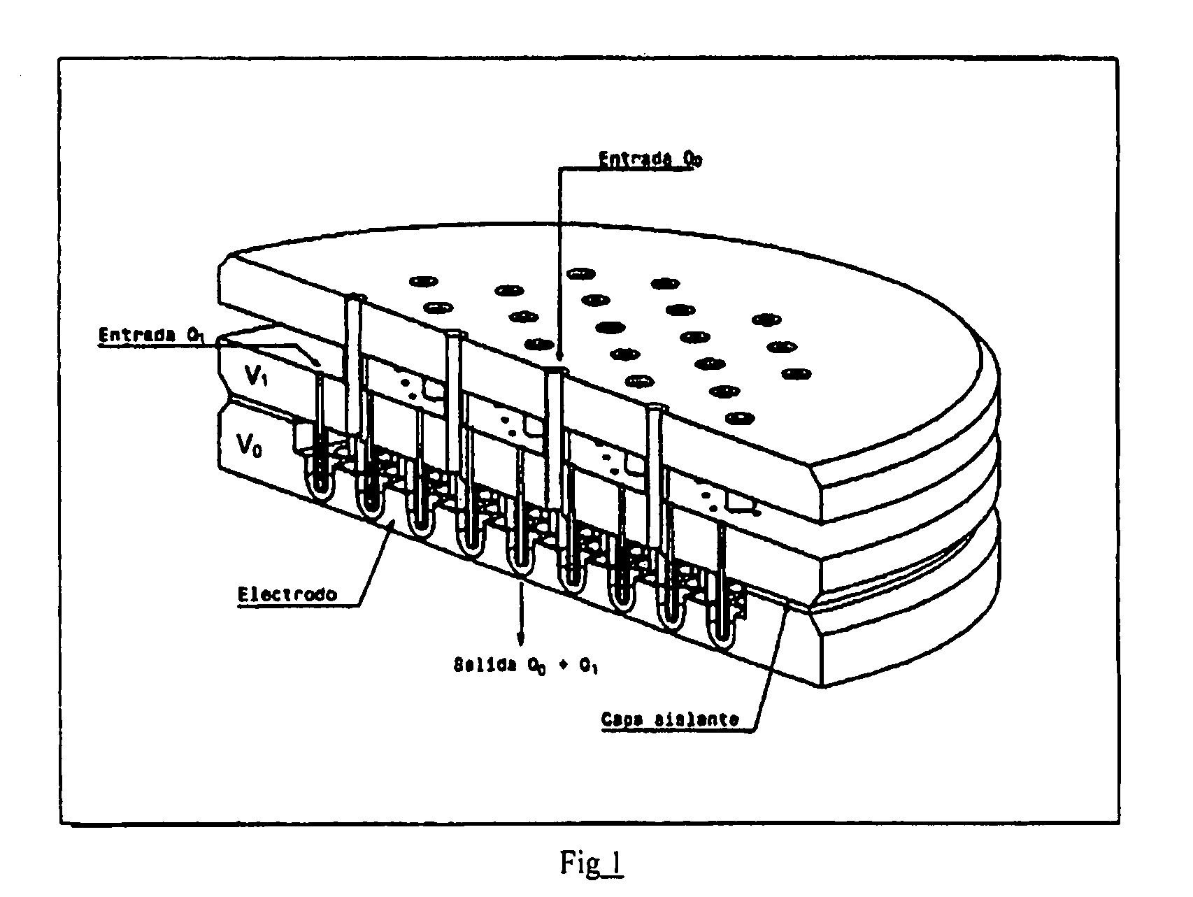
[0038]FIG. 1. Example of an embodiment of the device according to the invention, in the case where N=1, where the feed tubes are shown, as well as the multiple electrode (“Electrode”, 55 cells in this particular case) with its specific geometry, and the means used to supply a second fluid through the upper orifices of the upper element. Characteristic routes followed by the fluid being forced through the feed tubes are shown in yellow (Q1) while the routes of the surrounding fluid being forced through the device are shown in red (Q0) (this fluid is immiscible with the fluid being injected through the capillary tubes). Also shown are the electric potentials V1 and V2 in each element and the isolating layer between both elements.
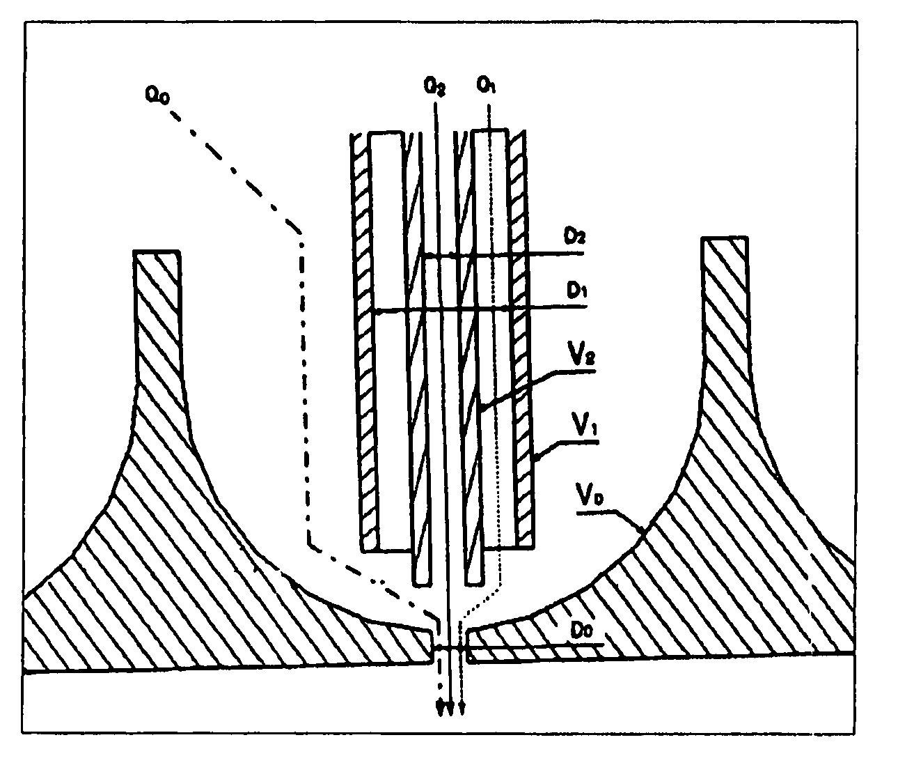
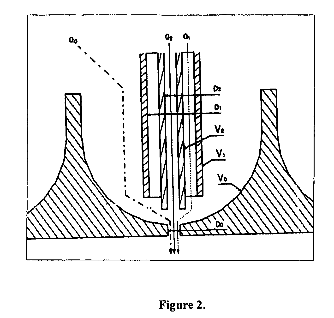
[0039]FIG. 2. Detail of an example of an embodiment of the invention in the case where N=2; two liquids 1 and 2 are forced (flow-rates Q1 and Q2), surrounded by a gas (flow-rate Q0).

Problems solved by technology

As a result, the jet is stabilized and flows steadily with a high flow-rate; such conditions are unattainable in the absence of a flow-focusing suction.
However, when a large number of needles are brought together and their relative distance diminishes, the electric field at their tips also decreases accordingly; this sets a limit on the packaging density of the needles in the design.

Method used


Image

  • Device for the production of capillary jets and micro-and nanometric particles
  • Device for the production of capillary jets and micro-and nanometric particles
  • Device for the production of capillary jets and micro-and nanometric particles

Examples


Embodiment Construction

[0045]In what follows, an embodiment example is described for the present invention; it does not attempt to be exhaustive nor to limit the scope of the present invention; it is only disclosed as an illustration, while the actual protection field of the invention is to be construed from the claims.

[0046]As shown in FIGS. 1 and 2, a device with 55 cells has been built, having a single feed tube per cell and thus transporting a single fluid; the material chosen was stainless steel AISI 316L. In order to shape the prototype, a PC-controlled CNC machining center has been used (EMCO PC Mill 155) as well as a precision lathe Pinacho. The electrode was fastened to the body of the device, which was built in AISI 316L stainless steel, with the help of six polyamide screws (Nylon) and a 0.1 mm thick Silicon RTV film, from Lockseal, meant to isolate the electrode from the body where the capillary tubes or feed tubes are set. The feed tubing is made in silica (Polymicro, USA) having an inner dia...


PUM

PropertyMeasurementUnit
sizeaaaaaaaaaa
sizeaaaaaaaaaa
sizeaaaaaaaaaa

Abstract

The invention relates to a method and devices for the production of capillary microjets and microparticles that can have a size of between hundreds of micrometers and several nanometers. The inventive method makes use of the combined effects of electrohydrodynamic forces, fluid-dynamic forces and a specific geometry in order to produce micro- and nano-capsules or fluid jets, single- or multi-component, which, upon disintegrating or splitting, form a significantly monodispersed spray of drops which have a controlled micro- or nanometric size and which can also comprise a specific internal structure, such as, for example, a nucleus which is surrounded by a cortex of a different substance or several concentric or non-concentric nuclei or vesicles which are surrounded by a cortex.

Description

FIELD OF THE INVENTION[0001]The invention describes a method and device for the production of capillary micro-jets and micro-particles, with a size ranging from some hundred microns to some nanometers. The method is based on the combined effect of electro-hydrodynamic forces, fluido-dynamic forces, and a specific geometry, to give rise to micro- and nano- fluid ligaments or jets; as these disintegrate or break up, a controllable and relatively monodisperse spray is formed, with drops in the micro- or nanometric range; in addition, the spray may display specific internal structure features, such as a nucleus surrounded by a heterogeneous shell, or a plurality of nuclei or vesiculae, which may be concentrical or not, surrounded by a shell.BACKGROUND OF THE INVENTION[0002]The electro-hydrodynamic atomization of liquids, or electrospray, has provided an essential tool for the biochemical analysis over the last decades (Electrospray Mass Spectrometry, o ESMS), following the discovery of ...

Claims


Application Information

Patent Timeline
Patent Type & Authority Patents(United States)
IPC IPC(8): B05B5/00B05B5/025B05B7/04B81C99/00
CPCB05B5/0255B05B7/04
Inventor GANAN CALVO, ALFONSO M.LOPEZ-HERRERA SANCHEZ, JOSE M.
Owner UNIV DE SEVILLA
Learn More