Method and apparatus for heat-treating an article and a fixture for use in the same

a technology of heat treatment and heat treatment, which is applied in the direction of electron beam welding apparatus, welding/cutting auxillary devices, auxillary welding devices, etc., can solve the problems of limiting the life of the fixture, the temperature at which the fixture is heat-treated is above the limit of softening the fixture, and the drawbacks of producing such hybrid structures

Inactive Publication Date: 2008-03-18
ROLLS ROYCE PLC
View PDF10 Cites 6 Cited by
  • Summary
  • Abstract
  • Description
  • Claims
  • Application Information

AI Technical Summary

Benefits of technology

[0006]The present invention seeks to provide an improved heat-treatme

Problems solved by technology

However drawbacks have been encountered in producing such hybrid structures.
However if the deposited feature is manufactured from titanium then the temperature at which it is heat-treated is above

Method used


Image

  • Method and apparatus for heat-treating an article and a fixture for use in the same
  • Method and apparatus for heat-treating an article and a fixture for use in the same
  • Method and apparatus for heat-treating an article and a fixture for use in the same

Examples


Embodiment Construction

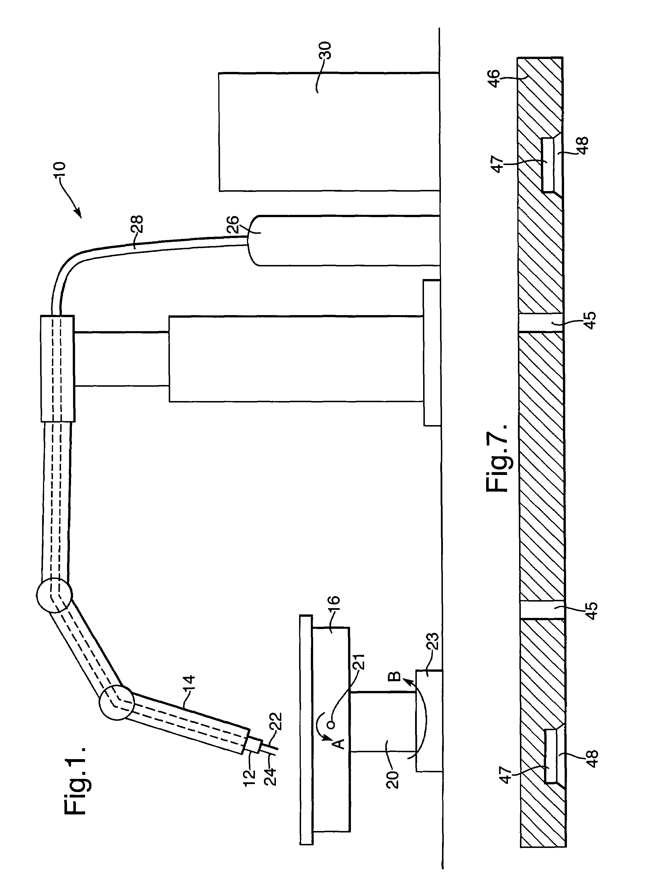
[0024]Referring to FIG. 1 apparatus (10) for forming an article (40) comprises a welding torch (12) attached to a computer controlled robot arm (14). A table (16) is mounted on a pedestal (20), which rotates about base (23), as indicated by arrow B. The table (16) is also capable of pivotal movement in the direction of arrow A around shaft (21) to maintain an angle of 90° between the torch (12) and the table (16).

[0025]A number of metal wires (22, 24) extend through the robot arm (14) from a supply in the form of a reel (not shown). The wires (22, 24) are fed from the reel to the welding torch (12) such that the ends of the wires (22, 24) extend just below the tip of the welding torch (12). The wires (22, 24) are manufactured from a suitable welding material such as titanium.

[0026]The apparatus also includes a supply of an inert gas, for example argon. The gas is supplied by a gas pipe (28), which extends through the robot arm (14) from a cylinder (26) to the welding torch (12).

[002...


PUM

PropertyMeasurementUnit
Temperatureaaaaaaaaaa

Abstract

A substrate (33) is clamped into a fixture (32) and material is deposited thereon to form a complex article (40). The article (40) produced is packed, using ceramic inserts (42) and a coating (41). The packing (42) ensures that the article (40) maintains its true shape and allows for expansion during the subsequent heat treatment process. The packed article (40), mounted on the fixture (32), is then placed in a box (44), encased in a granular material (43) and heated. It is heated to a temperature sufficient to relieve stresses and is maintained at this temperature for a time period such that the stresses in the article (40) are relieved.

Description

FIELD OF THE INVENTION[0001]The present invention relates to a method and apparatus for heat-treating an article and in particular complex articles manufactured from layers of deposited material. A fixture is also disclosed for holding the complex article during its manufacture and the subsequent heat-treatment.BACKGROUND OF THE INVENTION[0002]It is known to produce metal work pieces by the deposition of a weld material onto a base plate. The weld material can be deposited by any one of a number of techniques including laser welding, electron beam welding, metal inert gas welding (MIG) or tungsten inert gas welding (TIG). In MIG or TIG welding a welding torch is provided adjacent a base plate on which the work piece is to be produced. An electrode is provided within the weld torch such that when an electric current is passed therethrough an arc is formed between the weld torch electrode and the base plate. The arc generates heat allowing the welding to take place.[0003]In the MIG pr...

Claims


Application Information

Patent Timeline
IPC IPC(8): B29C71/02B23K9/04B23K10/02B23K15/00B23K26/34B23K35/32B23K37/04B23Q1/03B23Q3/10C21D1/30C21D1/44C21D1/70C21D9/00C21D9/50
CPCB23K9/044B23K15/0086B23K37/04B23K37/0461C21D1/30C21D1/70C21D9/0025B23K26/3206B23K26/3213B23K26/345B23K10/027B23K35/0261B23K35/325C21D9/50B23K35/383B23K26/32B23K26/342B23K2103/08B23K2103/14B23K2103/50
Inventor CLARK, DANIELSMITH, BARRY D
Owner ROLLS ROYCE PLC
Why Eureka
Try Eureka