Photonic bandgap fibre, and use thereof

a bandgap fibre and bandgap technology, applied in the field of optical fibres, can solve the problems of insufficient refractive index contrast to provide in-plane 2d pbg effects, structures are practically impossible to use, and the fabrication of prior art pbg fibres is hindered, so as to achieve high flexibility, strong dispersion, and large flexibility

Inactive Publication Date: 2008-03-25
CRYSTAL FIBRE AS
View PDF17 Cites 42 Cited by
  • Summary
  • Abstract
  • Description
  • Claims
  • Application Information

AI Technical Summary

Benefits of technology

[0050]In yet another preferred embodiment, the core feature spacing is smaller than the cladding feature spacing. The main advantage of this is the achievement of a higher flexibility when tailoring the mode-shape of light guided through the fibre. By using core features that are smaller than the cladding features, it is possible to increase the number of core features and thereby to provide a better mode shaping. For most applications, it is desired to have a mode-shape that is as close as possible to a gaussian shape, in order to reduce coupling losses at e.g. splicing to standard fibres.
[0064]In a further preferred embodiment, any of the core features and / or the cladding features comprise polymer(s), a material providing an increased third-order non-linearity, a photo-sensitive material, or a rare earth material. This preferred embodiment allows the realization of various applications, such as fibre laser, amplifiers, wavelength converters, optical switches, tuneable fibres and devices, etc. The use of polymer(s) as background material for the fibres allows potentially cheap and very flexible fabrication of the fibres covered by the present invention.

Problems solved by technology

Hence, materials such as air (with a refractive index of 1.0) and silica (with a refractive index of 1.45) do not provide sufficient refractive index contrast to provide in-plane 2D PBG effects.
In the above-mentioned reference Birks et al. teaches that high-index rods in a background material may also provide out-of-plane 2D PBGS, but that such structures are practically impossible to use since solid rods of silica surrounded by air may not be supported robustly in form of optical fibres.
One of the main reasons to the few number of experimental studies is related to difficulties in fabricating PBG fibres.
In particular, the fabrication of prior art PBG fibres is hindered by the difficulties in accurately controlling voids (typically air holes) in the fibres.
These difficulties concern the high demands for longitudinal uniformity of the fibres, a sufficient number of periods surrounding the core, high uniformity in the periodic arrangement of the cladding features, as well as very precise dimensioning of these cladding features.
At present, the above-mentioned requirements have proven difficult to meet for PBG fibre lengths of more than 50 metres.
It is a disadvantage of prior art PBG fibres incorporating voids that the voids and thereby the waveguiding properties of the PBG fibres are difficult to control during fabrication.
For compatibility with conventional, silica-based optical fibre technology, it is a disadvantage that prior art, silica-based PBG fibres comprise voids.
The low-index features (typically voids) in the core of prior art PBG fibres may result in problems such as mode mismatch between the guided mode of a PBG fibre and the guided mode of a conventional silica optical fibre, coupling losses due to reflections between the interface of two such fibres, and splicing difficulties for PBG fibres due to collapsing or expanding voids.
It is, therefore, a further disadvantage of prior art PBG fibres that the core region comprises material with a refractive index lower than that of the cladding background material.
In particular, it is a disadvantage of prior art PBG fibres that the core region comprises voids.
It is a further disadvantage of prior art PBG fibres comprising voids that the large refractive index difference between the core / cladding features and the background material results in a high sensitive towards minor structural inaccuracies for certain fibre properties.
For example, polarization effects, such as birefringence, are very difficult to eliminate in prior art PBG fibres due to the high index contrast between the constituting materials of the fibre.
As a result of this, prior art PBG fibres may exhibit large polarization mode dispersion (PMD) that cannot be tolerated for optical transmission fibres operating at high bit rates, such as at 10 Gbit / s or higher.

Method used


Image

  • Photonic bandgap fibre, and use thereof
  • Photonic bandgap fibre, and use thereof
  • Photonic bandgap fibre, and use thereof

Examples


Embodiment Construction

[0100]Further scope of applicability of the present invention will become apparent from the detailed description given hereinafter. However, it should be understood that the detailed description and specific examples, while indicating preferred embodiments of the invention, are given by way of illustration only, since various changes and modifications within the spirit and scope of the invention will become apparent to those skilled in the art from this detailed description.

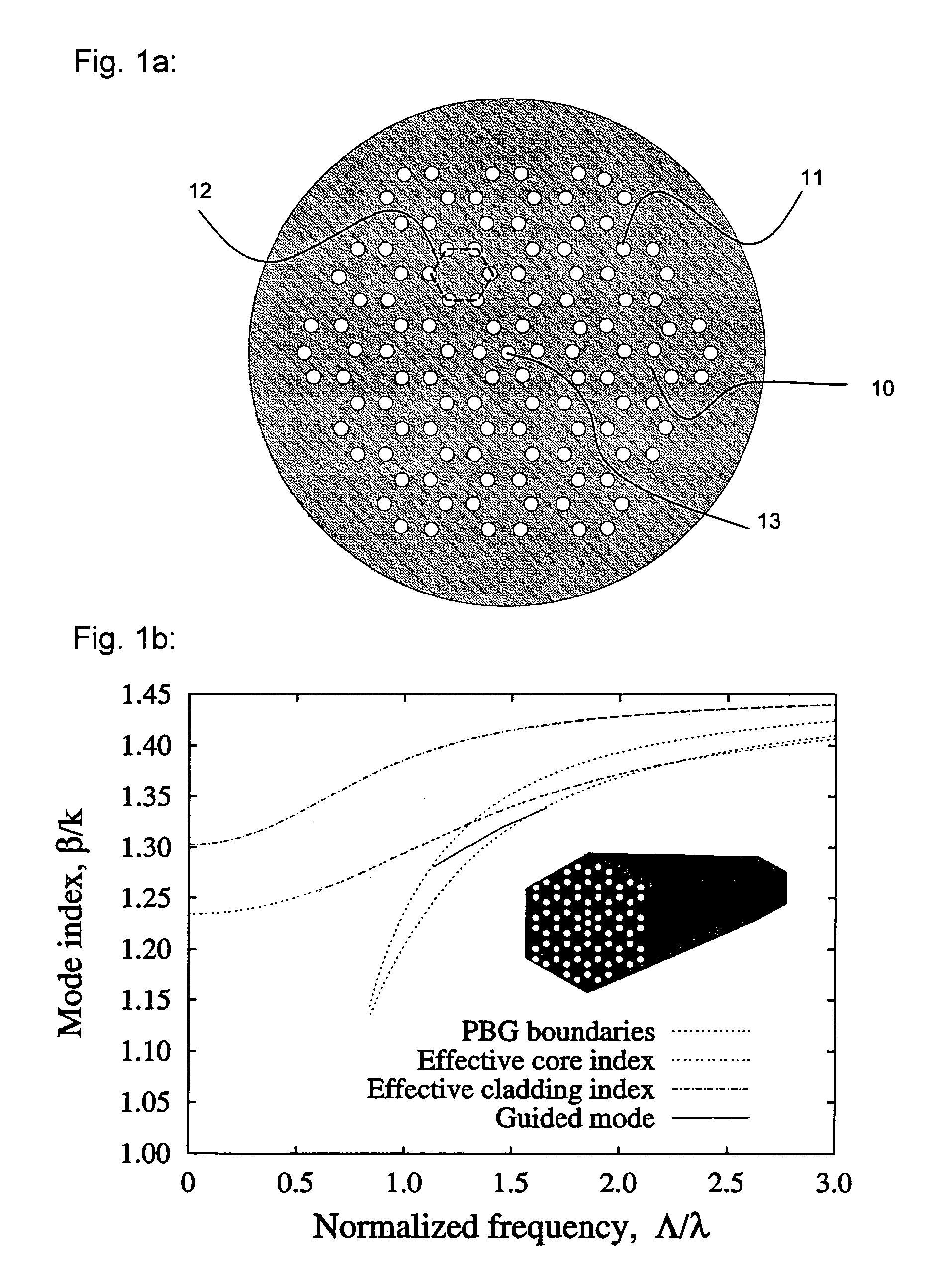
[0101]A typical air-silica PBG fibre known from the prior art is illustrated schematically in FIG. 1a. The figure shows a cross-section of the fibre. The fibre consists of a background material 10 and it is invariant in the longitudinal direction (the direction perpendicular to the illustrated cross-section). The fibre has a cladding region characterized by an array of low-index features 11 that run along the fibre axis. In the prior art, the most commonly used background material is silica and the features are m...


PUM

PropertyMeasurementUnit
refractive indicesaaaaaaaaaa
wavelengthsaaaaaaaaaa

Abstract

A mircrostructured optical fiber that guides light in a core region, where the fiber has a cladding region that includes a background material and a number of cladding features or elements that are elongated in the longitudinal direction of the fiber and have a higher refractive index than the cladding background material. The core region has a lower effective refractive index than the cladding, and the fiber may guide light in the core by photonic bandgap effects.

Description

[0001]This is a nationalization of PCT / DK02 / 00390 filed Jun. 7, 2002 and published in English.FIELD OF THE INVENTION[0002]The present invention relates to optical fibres that operate by photonic bandgap effects. The invention provides a new range of photonic bandgap (PBG) guiding optical fibres that comprise periodically arranged high-index cladding features and a core region with a lower effective refractive index than the refractive index of the cladding features. The present invention provides photonic bandgap fibres that may operate without the use of voids in the cladding, thereby simplifying fabrication of photonic bandgap fibres compared to prior art. The invention further provides photonic bandgap fibres with tuneable waveguiding properties, such as tuneable dispersion and tuneable polarization. The new fibres have a number of potential applications mainly in the field of fibre optical communication systems.BACKGROUND OF THE INVENTION[0003]Within the past few years, a signif...

Claims


Application Information

Patent Timeline
Patent Type & Authority Patents(United States)
IPC IPC(8): G02B6/00G02B6/02G02B6/32C03B37/012G02B6/10
CPCC03B37/01217C03B37/0122G02B6/02323G02B6/02338G02B6/02347G02B6/0238C03B2201/31C03B2203/42G02B6/0239G02B6/105
Inventor BROENG, JESLIBORI, STIG EIGIL BARKOUBJARKLEV, ANDERS
Owner CRYSTAL FIBRE AS
Why Eureka
Try Eureka