Relative pressure control system and relative flow control system

a technology of relative flow control and control system, which is applied in the direction of fluid pressure control, process and machine control, instruments, etc., can solve problems such as the device entering a runaway sta

Active Publication Date: 2008-04-08
CKD +1
View PDF13 Cites 97 Cited by
  • Summary
  • Abstract
  • Description
  • Claims
  • Application Information

AI Technical Summary

Benefits of technology

[0045]Consequently, according to the relative pressure control system and relative flow control system of the present invention, with the simple construction having the single flowline for flowing the operation gas, the etching gas can be accurately regulated for the pressure ratio and can be securely drained from the operating gas pipeline in case of emergency.
[0047]The pressure detected by the each respective pressure sensor is applied for data of a valve model to obtain the operation pressure that is exerted on the specified air operated valve, thereby to perform feed forward control of the open and close operations of the air operated valve. Consequently, the amount of control time for the air operated valve is reduced, and the processing capacity of the overall system can be enhanced.
[0050]When the operation gas is supplied in the state where all proportional control valves are fully opened, the output pressure of the each respective air operated valve is detected at a fixed interval by the pressure sensors, and then it is determined whether the pressure ratio exceeds a specified value. If the specified value is exceeded, the conductance is not reproduced to be the same as in an initial state, and hence abnormality is likely to be occurring with high probability, so that operation is carried out to detect such abnormality. Thereby, the relative flow control system and the relative pressure control system are enabled to quickly detect failure with components such as the operation gas pipeline.
[0051]The following briefs effects of the relative pressure control system using the proportional control means and the fixed orifice means. When an operation gas flowing through the same flowline is supplied to the proportional control means and the fixed orifice means, the operation gas is output from the proportional control means and the fixed orifice means. Output pressures of the proportional control means and the fixed orifice means are detected by the pressure sensors, and the valve openings of the proportional control means are regulated in accordance with the results of detection. Thereby, the output pressures of the fixed orifice means are relatively varied, and the operation gas is then output at a predetermined division ratio from the proportional control means and the fixed orifice means.
[0053]Consequently, according to the relative flow control system of the present invention, with the simple construction having the single flowline for flowing the operation gas, the operation gas can be accurately regulated for the pressure ratio and can be securely drained from the operating gas pipeline in case of emergency. Further, cost reduction can be implemented by reducing the number of components, such as the proportional control means and hard-interlock mechanism.
[0057]Thus, according to the case where the fixed-opening closing amount is set to sufficiently include such a noncontrollable zone, even when the control objective valve is determined by determining the threshold value, the control can be performed without problems.

Problems solved by technology

Suppose that the control device has entered a runaway state to the extent of not being able to recognize the operational state of the each respective air operated valve.

Method used


Image

  • Relative pressure control system and relative flow control system
  • Relative pressure control system and relative flow control system
  • Relative pressure control system and relative flow control system

Examples


first embodiment

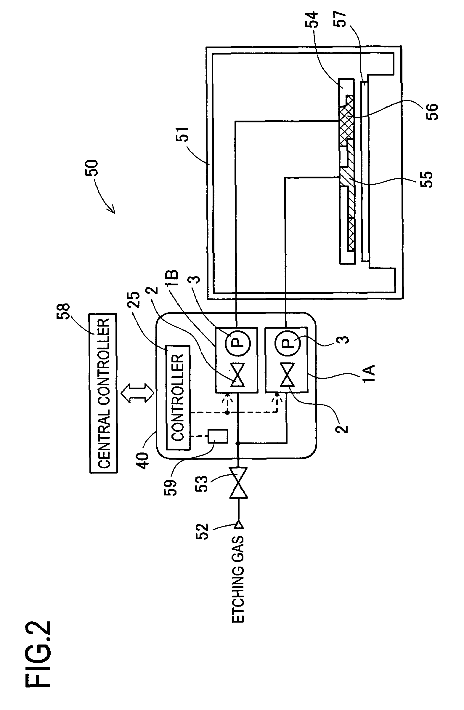
[0095]To begin with, a first embodiment of the present invention will be described herebelow with reference to the drawings. FIG. 2 is a schematic diagram of an overall configuration of an etching gas supply system 50.

[0096]The etching gas supply system 50 includes a chamber 51 that is used to perform etching. A supply source 52 of the etching gas is connected through a gas supply valve 53 and a relative pressure control system 40 to an etching shower 54 disposed in the chamber 51. The etching shower 54 is disposed above one wafer 57 placed in the chamber 51, and an edge shower 56 is provided around a center shower 55.

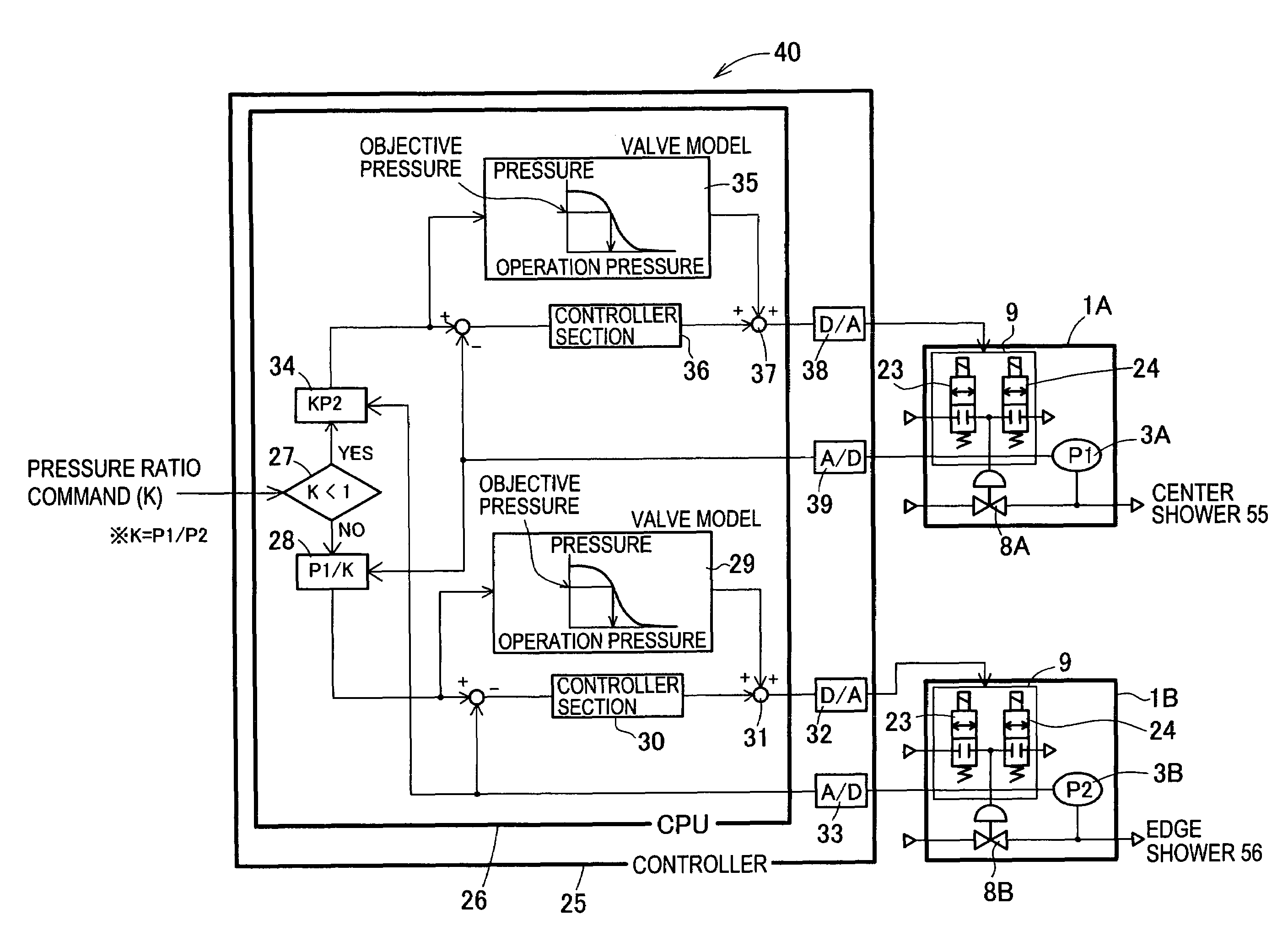
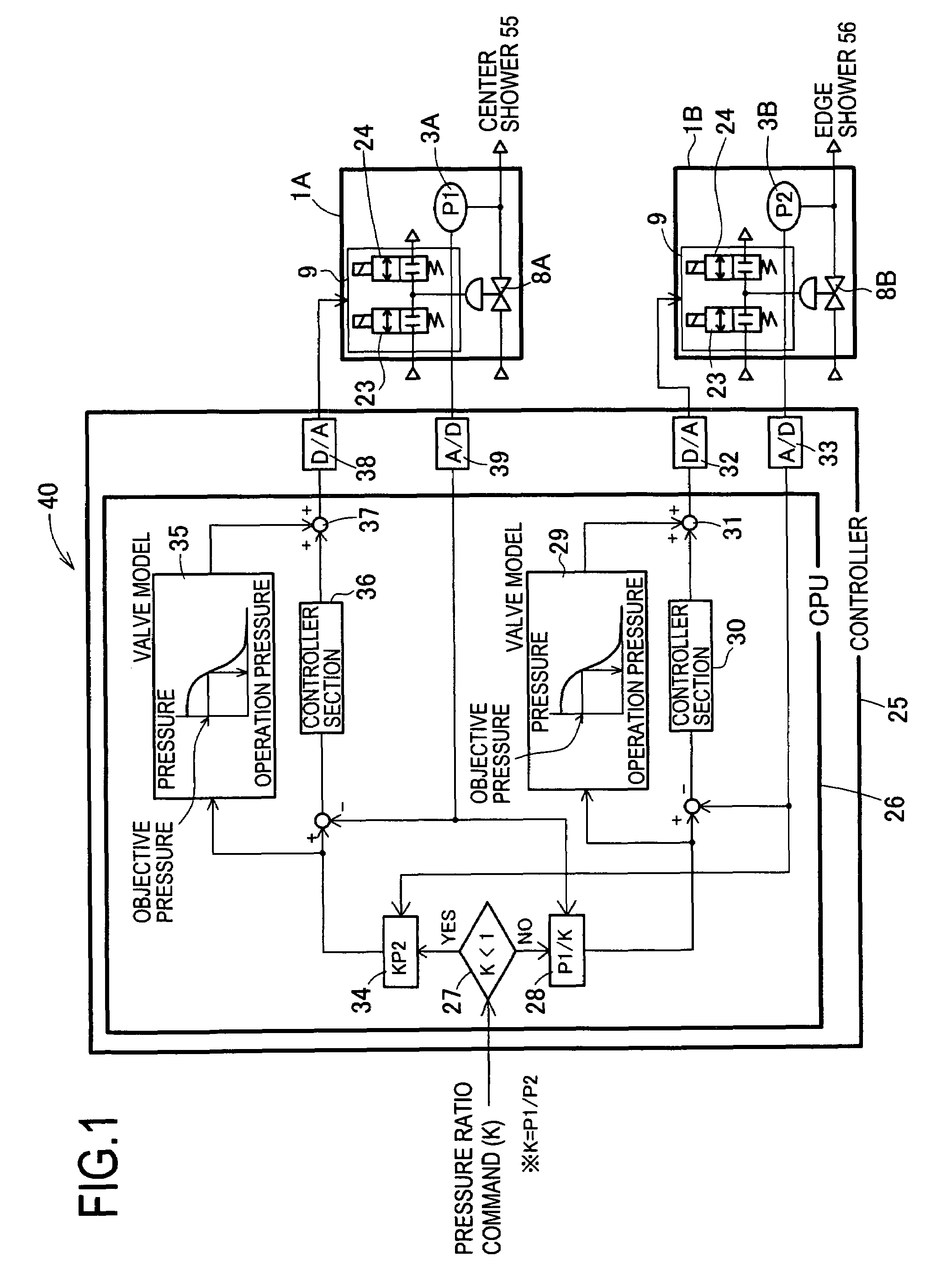
[0097]The relative pressure control system 40 includes a pressure control device 1A connected to the center shower 55, and a pressure control device 1B connected to the edge shower 56. The pressure control devices 1A and 1B each include a pneumatic pressure control valve 2 and a pressure sensor 3, and are respectively connected to a controller 25 (each corresponding to...

second embodiment

[0134]A second embodiment of the present invention will be described herebelow with reference to the drawings. FIG. 9 is a schematic diagram of an overall configuration of a relative flow control system 45A.

[0135]The relative flow control system 45A of the present embodiment is used for an etching process of semiconductor manufacturing steps. The relative flow control system 45A is configured in the manner that a plurality of flow control devices 41A to 41D are connected to the relative pressure control system 40 of the first embodiment. The flow control devices 41A to 41D, respectively, are connected to operation gas supply sources of, for example, O2, Ar, C4F8, and CO. The respective flow control devices 41A to 41D are configured such that flow control valves 42A to 42D for performing the flow rate regulation of the operation gas are series connected to flow rate sensors 43A to 43D (each corresponding to “flow rate sensing means”). The flow control devices 41A to 41D, respectively...

third embodiment

[0139]A third embodiment of the present invention will be described herebelow. FIG. 10 is a schematic diagram of an overall configuration of a relative flow control system 45B.

[0140]In the relative flow control system 45B of the present invention, a relative pressure control system 70 controls the division ratio by using a single piezo-electric valve 72 (corresponding to “proportional control means”) and an orifice 73 (corresponding to “orifice means”). In these respects, the relative flow control system 45B is different from the relative pressure control system 40 of the first and second embodiments that controls the division ratio by using two air operated valves 8. The following will describe in detail portions different from the first and second embodiments, but omit description of portions common thereto. Portions common to the first and second embodiments are shown in the drawings with the same reference characters.

[0141]The relative pressure control system 70 is connected to ...


PUM

PropertyMeasurementUnit
pressureaaaaaaaaaa
pressureaaaaaaaaaa
relative pressureaaaaaaaaaa

Abstract

Provided is a relative pressure control system has a simple configuration, but enables accurate regulation of a division ratio of an operation gas, and concurrently makes it possible to securely drain the operation gas from an operation gas pipeline in case of emergency. The system includes a plurality of air operated valves of a normally open type that are connected to an operation gas pipeline supplied with an operation gas; pressure sensors that are series connected to the respective air operated valves and that detect output pressures of the respective air operated valves; a controller that controls operation pressures of the respective air operated valves in accordance with the pressures detected by the pressure sensors; and a hard interlock solenoid valve that correlates the plurality of air operated valves to one another so that at least one of the plurality of air operated valves is normally opened. In the configuration, an opening of a specified one of the plurality of air operated valves is regulated, the operation gas is output at a predetermined division ratio.

Description

[0001]This is a Continuation of International Application No. PCT / JP2004 / 007819 filed Jun. 4, 2004, which claims the benefit of Japanese Patent Application No. 2003-163948 filed Jun. 9, 2003. The entire disclosure of the prior application is hereby incorporated by reference herein in its entirety.BACKGROUND OF THE INVENTION[0002]1. Field of the Invention[0003]The invention relates to a relative pressure control system and a relative flow control system that control a supplied flow of operating gas to be divided for two systems and to be output at a predetermined division ratio.[0004]2. Description of the Related Art[0005]Conventionally known etching gas supply systems include those of the type that supplies a low-pressure etching gas to a center area and edge area of a wafer. FIG. 29 is a schematic diagram of an overall configuration of a conventional etching gas supply system 300. FIG. 30 is a selectively enlarged cross sectional view of a focus ring 307 shown in FIG. 29.[0006]The ...

Claims


Application Information

Patent Timeline
Patent Type & Authority Patents(United States)
IPC IPC(8): G05D11/13G05D16/20
CPCG05D16/206Y10T137/87877Y10T137/0396Y10T137/7761
Inventor KONO, TETSUJIRODOI, HIROKIITO, MINORUNAGAOKA, HIDEKIITO, KEIKIENDO, HIROKISHIMAZU, TSUYOSHIHIROSE, JUNKATSUMATA, OSAMUMIURA, KAZUYUKIKITAZAWA, TAKASHI
Owner CKD
Why Eureka
Try Eureka