Flying-adder frequency synthesizer-based digital-controlled oscillator and video decoder including the same

a digital control circuit and adder frequency technology, applied in the field of integrated circuits, can solve the problems of jitter and noise, the frequency of the output clock signal is often coupled with the output clock signal, and the scaling is limited by the performance of the control circuit, so as to accurately measure the frequency of the incoming clock signal

Active Publication Date: 2008-04-08
TEXAS INSTR INC
View PDF5 Cites 23 Cited by
  • Summary
  • Abstract
  • Description
  • Claims
  • Application Information

AI Technical Summary

Benefits of technology

[0032]It is an object of this invention to provide a digital-control oscillator (DCO) that can implement a large frequency multiplier without vulnerability to frequency drift.
[0034]It is a further object of this invention to provide circuitry that can accurately measure the frequency of an incoming clock signal, such as a sync frequency in a video signal, and to use this measured frequency to establish an operating mode.
[0035]It is a further object of this invention to provide an all-digital phase-locked loop (ADPLL) circuit that can precisely control the sample times of multiple input signals.

Problems solved by technology

In this way, the number of synthesis paths can be increased arbitrarily, with the scaling limited by the performance of control circuits for the output multiplexer.
Accordingly, if significant jitter or noise is present on the input clock signal, this jitter and noise tends to couple to the output clock signal.
This is of course undesirable.
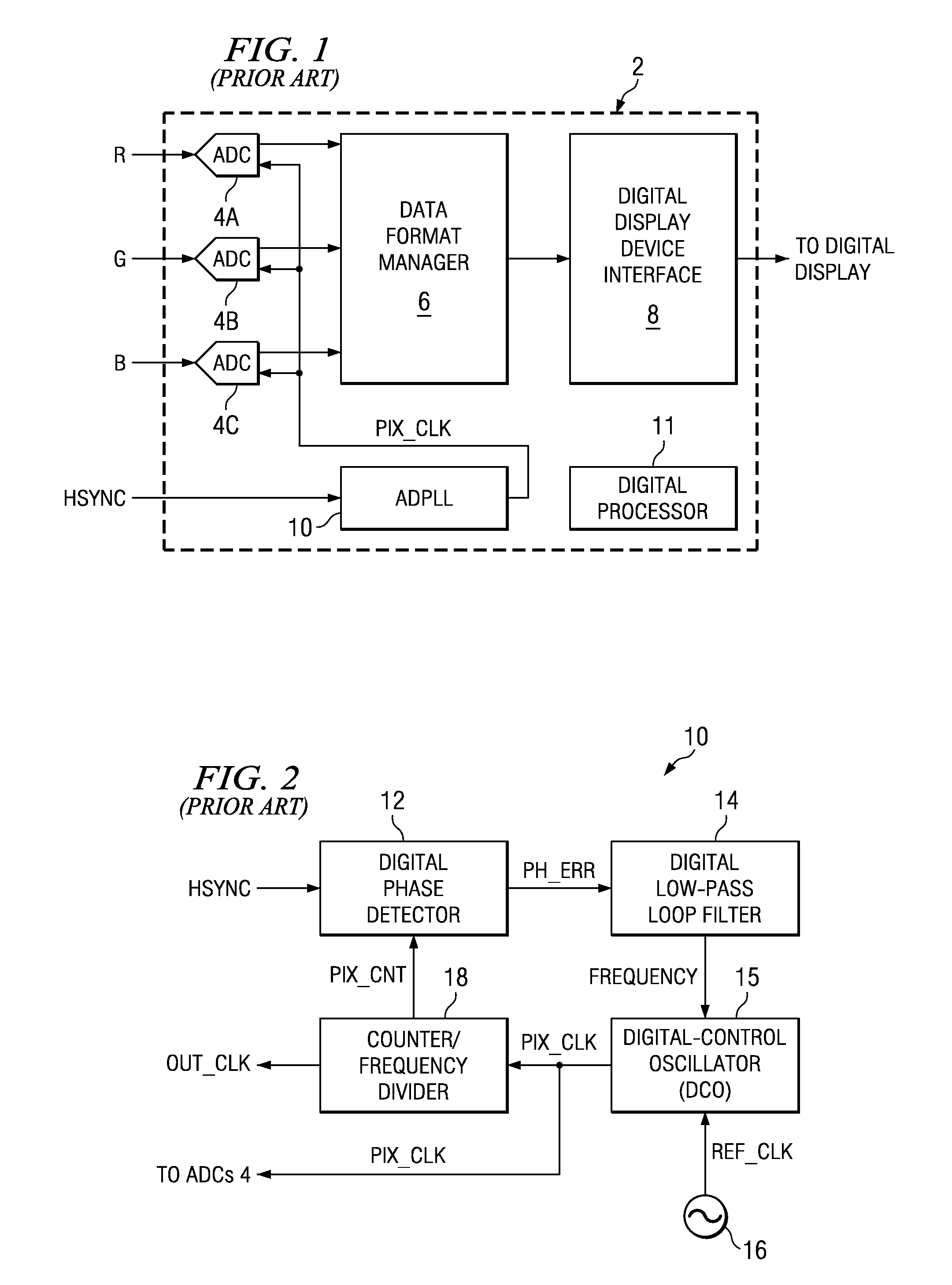
However, in many circuit applications, such as in video decoders, jitter and noise on the incoming clock signal cannot be avoided, and therefore it is difficult in such applications to digitally generate a stable and clean output clock signal.
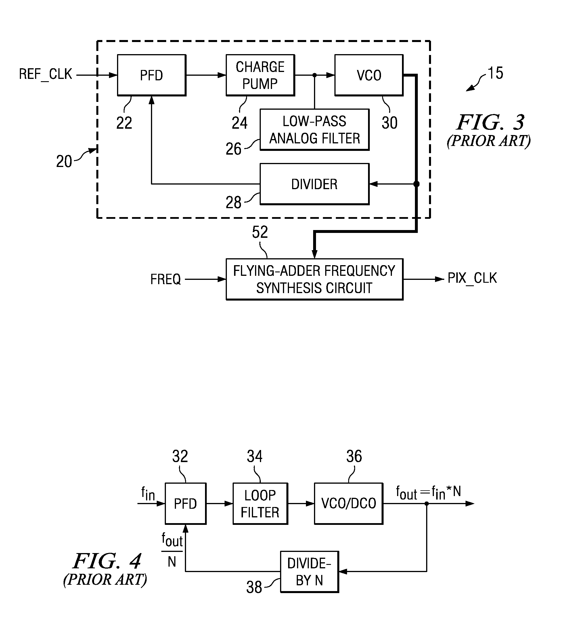
Furthermore, conventional DCO and PLL circuits are typically not able to generate a stable and high-fidelity clock signal that has a frequency at a large multiple of the input clock signal. FIG. 4 illustrates a conventional PLL-based frequency multiplier.
It has been observed, however, that the maximum value of multiplier N that can still result in a stable output frequency fout is limited in this conventional architecture of FIG. 4.
This slow update rate generally results in drift of the output frequency fout.
Especially in applications, such as video decoders, that rely upon stable clock signal frequencies for high fidelity operation, significant frequency drift cannot be tolerated.

Method used


Image

  • Flying-adder frequency synthesizer-based digital-controlled oscillator and video decoder including the same
  • Flying-adder frequency synthesizer-based digital-controlled oscillator and video decoder including the same
  • Flying-adder frequency synthesizer-based digital-controlled oscillator and video decoder including the same

Examples


Embodiment Construction

[0053]The present invention will be described in connection with its preferred embodiment, namely as implemented into a video decoder, considering that this invention provides particular benefit in such an application. However, those skilled in the art having reference to this specification will readily recognize that this invention will have benefit in any digital circuit or system that utilizes a phase-locked loop, or indeed that could benefit from a digitally-generated stable clock signal. Accordingly, it is to be understood that the following description is provided by way of example only, and is not intended to limit the true scope of this invention as claimed.

[0054]FIG. 5 illustrates an exemplary digital circuit, namely video decoder 52, into which the preferred embodiment of this invention is implemented. The overall function of video decoder 52 is to convert an input analog signal, received from any one or more of a number of conventional video signal sources (antenna, tuner...


PUM


Abstract

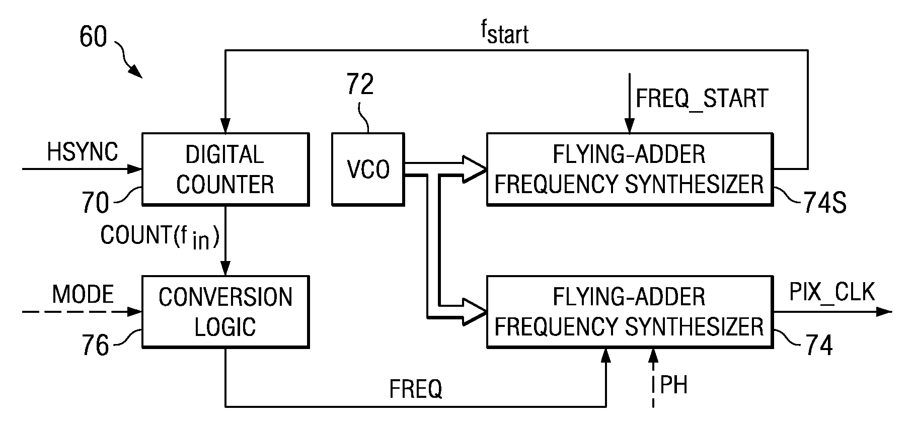
A video decoder (52, 152) including a digital-control oscillator (DCO) (60, 160) is disclosed. The DCO (60, 160) includes a first flying-adder frequency synthesis circuit (74S) that measures an input signal frequency, such as the horizontal sync frequency of an input video signal. A frequency control word (FREQ) is generated in response to this input signal frequency, and is applied to a second flying-adder frequency synthesis circuit (74), which in turn selects the appropriate phases for leading and trailing edges of the output clock signal (PIX_CLK). Phase tuning of the output clock signal (PIX_CLK) can be effected by using an alternate flying-adder frequency synthesis circuit (74′) architecture, in combination with a phase signal (PH) generated by a digital controller (61). Multiple phase-tuned sample clocks (PIX_CLK_A, PIX_CLK_B, PIX_CLK_C) can be similarly generated from multiple flying-adder frequency synthesis circuits (174A, 174B, 174C), each controlled by the frequency control word (FREQ) and a corresponding phase signal (PHA, PHB, PHC). Video mode control logic (65, 165) can also be implemented by way of a similar DCO architecture. The DCO (60) may be used to generate a clock signal at a large frequency multiple relative to the input signal, outside of the video decoder context.

Description

CROSS-REFERENCE TO RELATED APPLICATIONS[0001]This application claims priority, under 35 U.S.C. §119(e), of Provisional Application No. 60 / 539,423, filed Jan. 26, 2004.STATEMENT REGARDING FEDERALLY SPONSORED RESEARCH OR DEVELOPMENT[0002]Not applicable.BACKGROUND OF THE INVENTION[0003]This invention is in the field of integrated circuits, and is more specifically directed to phase-locked loop circuits.[0004]As is fundamental in the art, many modern electronic systems include numerous integrated circuits that operate in conjunction with one another. For example, consumer-oriented systems such as televisions and home theaters include video decoders for decoding an input video signal into digital video output signals that are synchronized with a synchronization pulse contained within the incoming video signal itself. Modern spread-spectrum communications transmitters and receivers require the generation of high-frequency clock signals for the modulation and demodulation, respectively, of...

Claims


Application Information

Patent Timeline
Patent Type & Authority Patents(United States)
IPC IPC(8): H04L7/00H04L7/04H03L7/00H04N5/06
CPCH03L7/00
Inventor XIU, LIMINGMEINERS, JASON
Owner TEXAS INSTR INC
Why Eureka
Try Eureka