
Laser-supported reproduction method

a technology of laser and reproduction method, which is applied in the direction of printing process, decorative arts, domestic objects, etc., can solve the problems of long equipment setting time, high cost, and inconvenient process, and achieves a high level of absorption, facilitates galvanic shaping of diffractive structure of master, and improves the effect of absorption

Inactive Publication Date: 2008-04-15
LEONHARD KURZ STIFTUNG & CO KG
View PDF18 Cites 1 Cited by
  • Summary
  • Abstract
  • Description
  • Claims
  • Application Information

AI Technical Summary

Benefits of technology

[0008]The object of the present invention is to provide a process and an apparatus which permit the production of preferably individualised markings on a substrate, preferably a film, involving a low level of apparatus expenditure.
[0025]With the apparatus according to the invention, partial regions of a stamping mold can be selected for the shaping operation targetedly by the radiation and thus the markings formed from the shapings of the partial regions are of an individualised configuration. It is particularly advantageous in that respect that the individualised identification in the form of the selection of the regions together with a security feature, more specifically for example the diffractive regions, are transferred by a common replication operation. In addition the apparatus according to the invention, by virtue of the continuous, non-cyclic mode of operation, permits economical production.
[0047]In a further advantageous configuration the replication apparatus has a pressure mold of metal film, in particular of nickel or a nickel compound. Galvanic shaping of a diffractive structure of a master is facilitated by the use of metal films of nickel or nickel compounds. As alternatives to those materials, it is also possible to use a material which, for the wavelength of the laser radiation used, has a particularly high level of absorption and in particular a higher level of absorption than nickel. An advantage with that configuration is that the radiated energy required, for producing the latent heat image on the replication apparatus, preferably on the replication surface, is markedly reduced. Accordingly it would be possible to use lasers which are of lower power and thus less expensive in the apparatus.

Problems solved by technology

Production of the mold is technically very demanding and also cost-intensive by virtue of the fine diffractive or holographic structures.
On the one hand a large number of individualised masters would have to be produced, which is highly cost-intensive, while secondly the molds have to be respectively interchanged in the replication apparatuses, which would result in very long equipment setting times. As alternatives, processes and apparatuses are known, which shape only partial regions of a mold in order to produce individualised security features.
That process is consequently limited by virtue of the fact that it involves a low level of local resolution.
A limitation with this process and apparatus is that the replication apparatus is in the form of a stamping punch.
This means that the process is limited to a cyclic mode of processing, which is contrary to the attainment of a high level of productivity.

Method used


Image

  • Laser-supported reproduction method
  • Laser-supported reproduction method
  • Laser-supported reproduction method

Examples


second embodiment

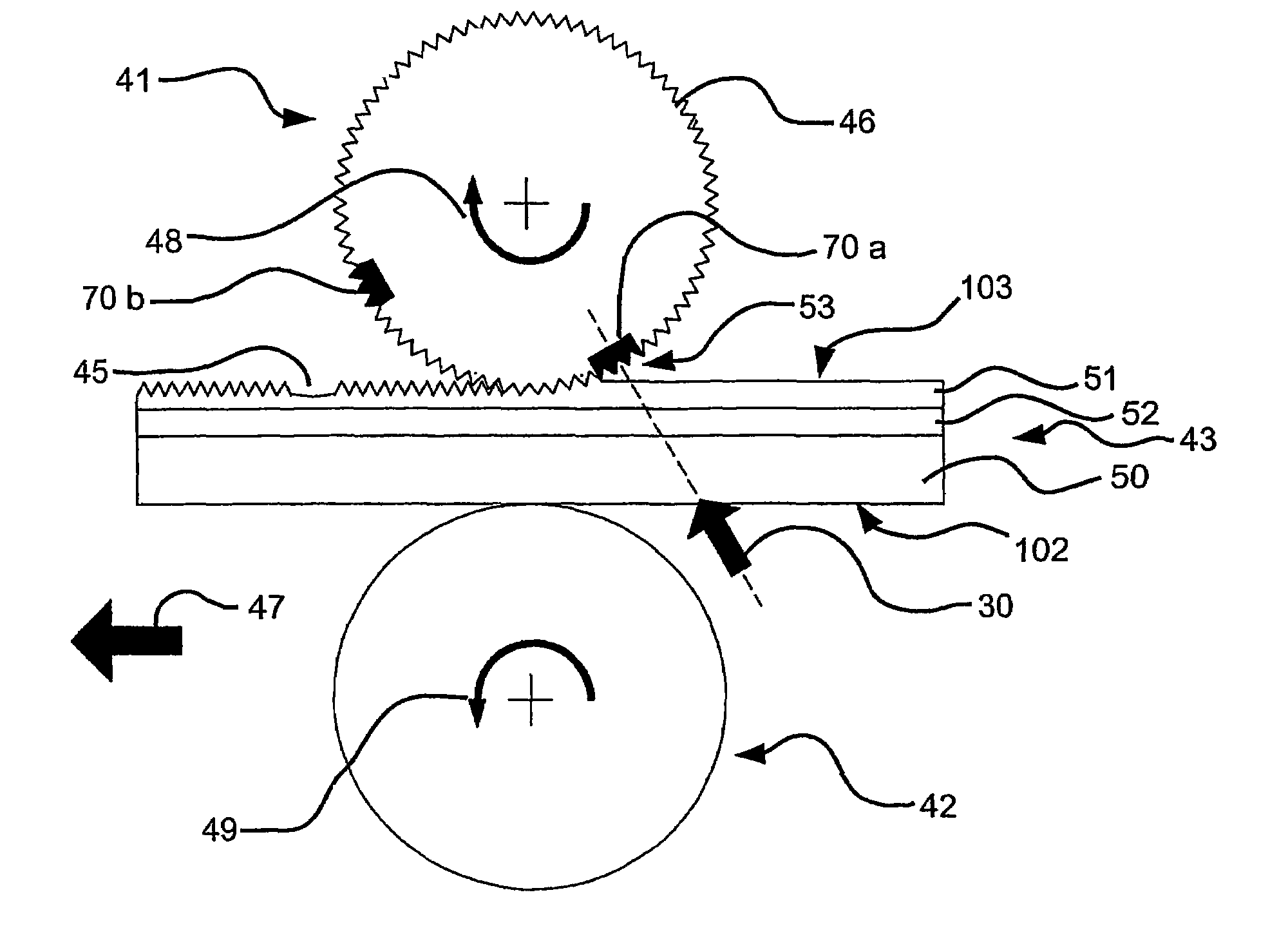
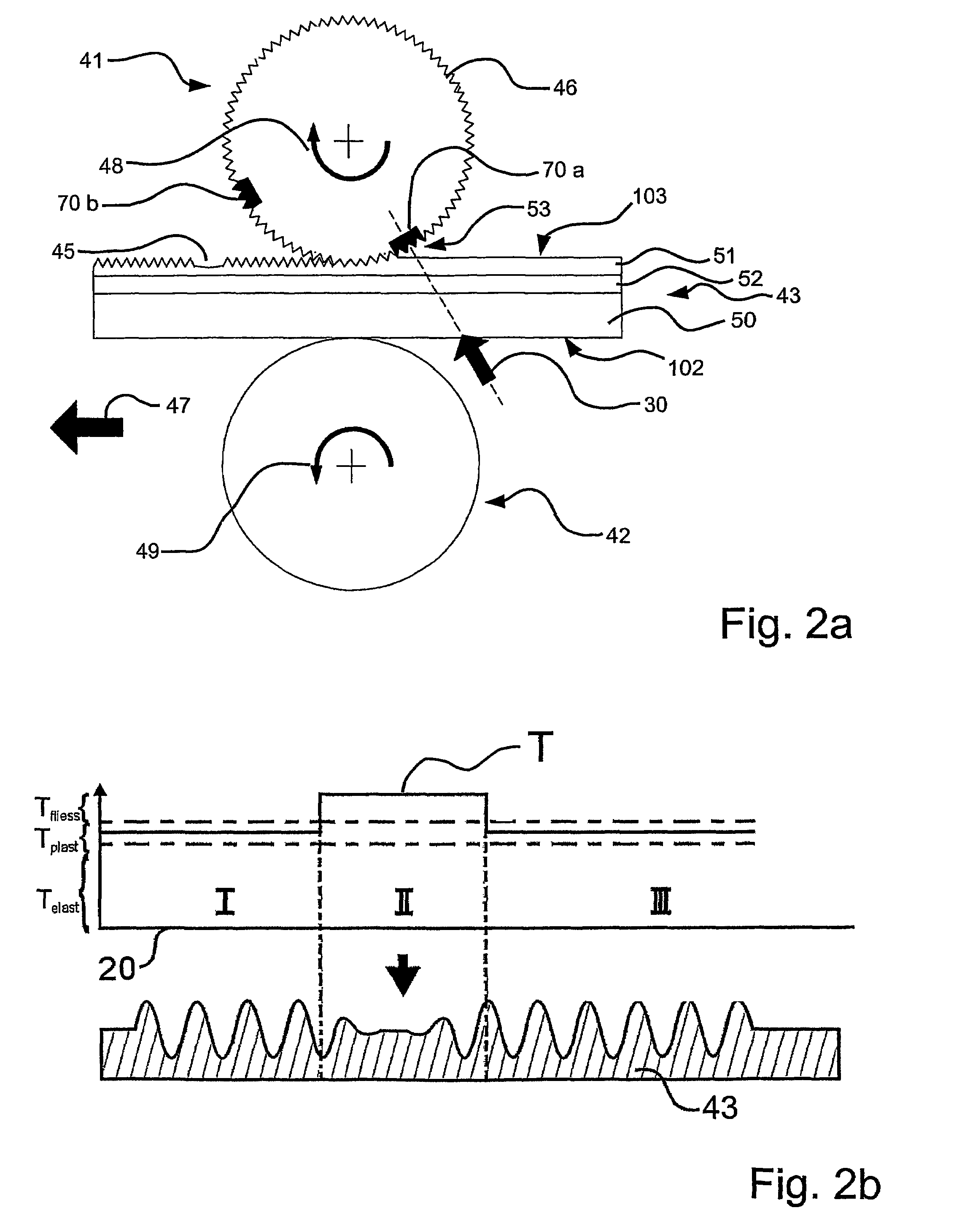
[0097]In this second embodiment of the process, only the regions of the replication surface which are complementary to the replication surface portions 70a, b irradiated with the laser beam 30, that is to say which are complementary to the heat combination regions, are shaped.

[0098]The extinction of a latent heat image produced in that way on the replication surface can be effected in a similar manner to the extinction procedure described with reference to FIG. 1a.

[0099]The principle of carrying out the process as shown in FIG. 2a is again diagrammatically shown in FIG. 2b in the same view as in FIG. 1b, wherein therefore the temperature pattern T is different from that shown in FIG. 1b.

[0100]The temperature profile T in FIG. 2b of the replication surface on passing through the replication gap 53 is in the plastic temperature range Tplast in the regions I and III, whereas in the region II the temperature is within the flow temperature range Tfliess.

[0101]In the region I, upon cont...

first embodiment

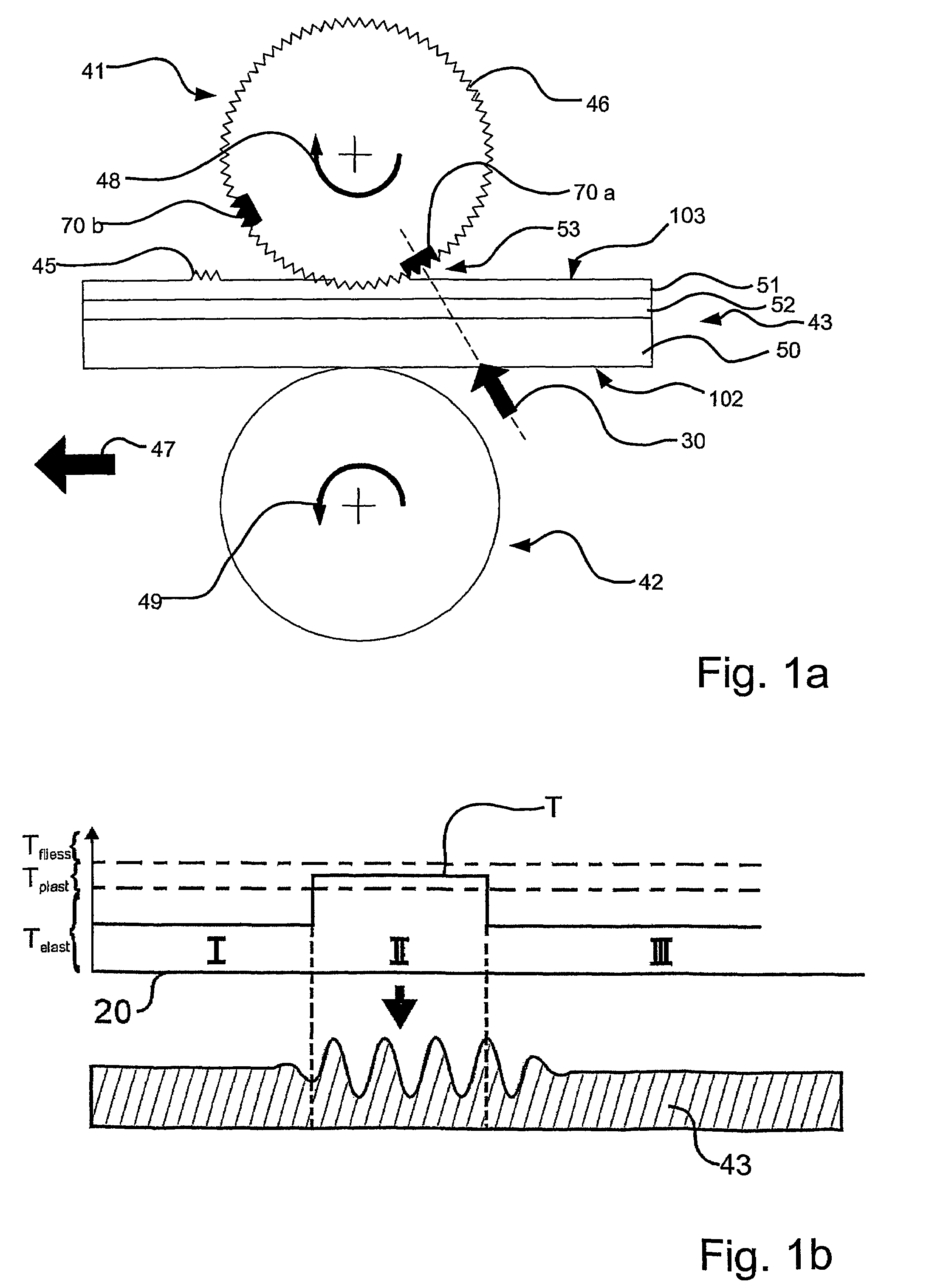
[0119]The process for producing a marking and control of the laser beam 30 as well as structural or functional features are similar to the configurations and description relating to the apparatus in FIG. 1a so that it is also possible to produce positive and negative images with the apparatus of FIG. 6a.


PUM

PropertyMeasurementUnit
angleaaaaaaaaaa
spacing angleaaaaaaaaaa
temperatureaaaaaaaaaa

Abstract

The invention concerns an apparatus and a process for producing a marking on a substrate. Substrates marked in that way are applied to documents such as for example credit cards, personal identity cards or banknotes as security features for affording protection from forgery. Embodiments of these security features have diffractive or holographic structures. Production of the markings is produced by shaping from a mold. A change in the configuration of the marking is possible by changing the mold, which is time-consuming. The new apparatus and the new process are intended to permit the production of individualised markings on a substrate at a low level of apparatus expenditure. The new apparatus has a replication apparatus, in the form of a replication roller, having a replication surface, a device for producing a radiation and a counterpressure apparatus with a counterpressure surface, wherein a substrate is arranged between the replication surface of the replication apparatus and the counterpressure surface of the counterpressure apparatus in such a way that a shaping region of the replication surface is shaped on to the substrate in a contact region between the replication surface and the substrate.

Description

CROSS-REFERENCE TO RELATED APPLICATIONS[0001]This application is a National Phase application of International Application No. PCT / DE2003 / 002670 filed Aug. 8, 2003, which claims priority based on German Patent Application No. 102 36 597.0, filed Aug. 9, 2002, and German Patent Application No. 102 50 476.8, filed Oct. 30, 2002, all of which are incorporated herein by reference.BACKGROUND OF THE INVENTION[0002]The invention concerns a process for producing a marking, for example digits, letters, surface patterns, surface images or decoration, on a substrate, preferably a film, in particular a transfer film, wherein energy in the form of radiation, preferably laser radiation, is introduced from a controllable energy source into a replication surface of a replication apparatus to produce at least one shaping region and wherein the shaping region of the replication surface is shaped on to the substrate by the replication apparatus contacting the substrate under pressure, and an apparatus...

Claims


Application Information

Patent Timeline
Patent Type & Authority Patents(United States)
IPC IPC(8): B44C1/24B29C59/04B29C59/00B29C59/02B41M3/14G03H1/02G03H1/08G03H1/30
CPCB29C59/022G03H1/028G03H1/08G03H1/30G03H1/0476B29C2059/023B29C2791/009B41M3/14
Inventor LUTZ, NORBERT
Owner LEONHARD KURZ STIFTUNG & CO KG
Learn More