

Rapid self-repairing and unsinkable watercraft
- Summary
- Abstract
- Description
- Claims
- Application Information
AI Technical Summary
Benefits of technology
Problems solved by technology
Method used
Image

Examples
Embodiment Construction
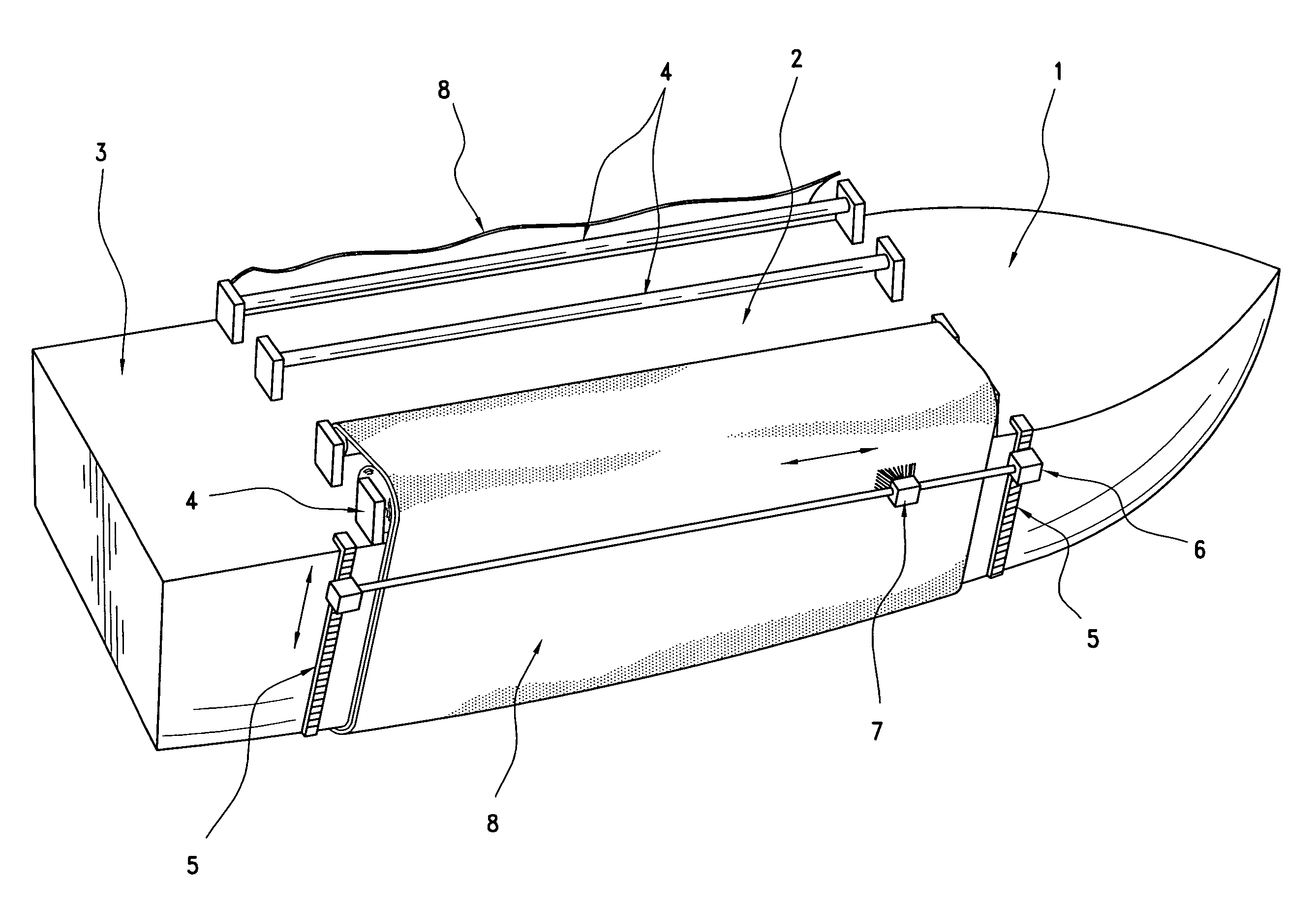
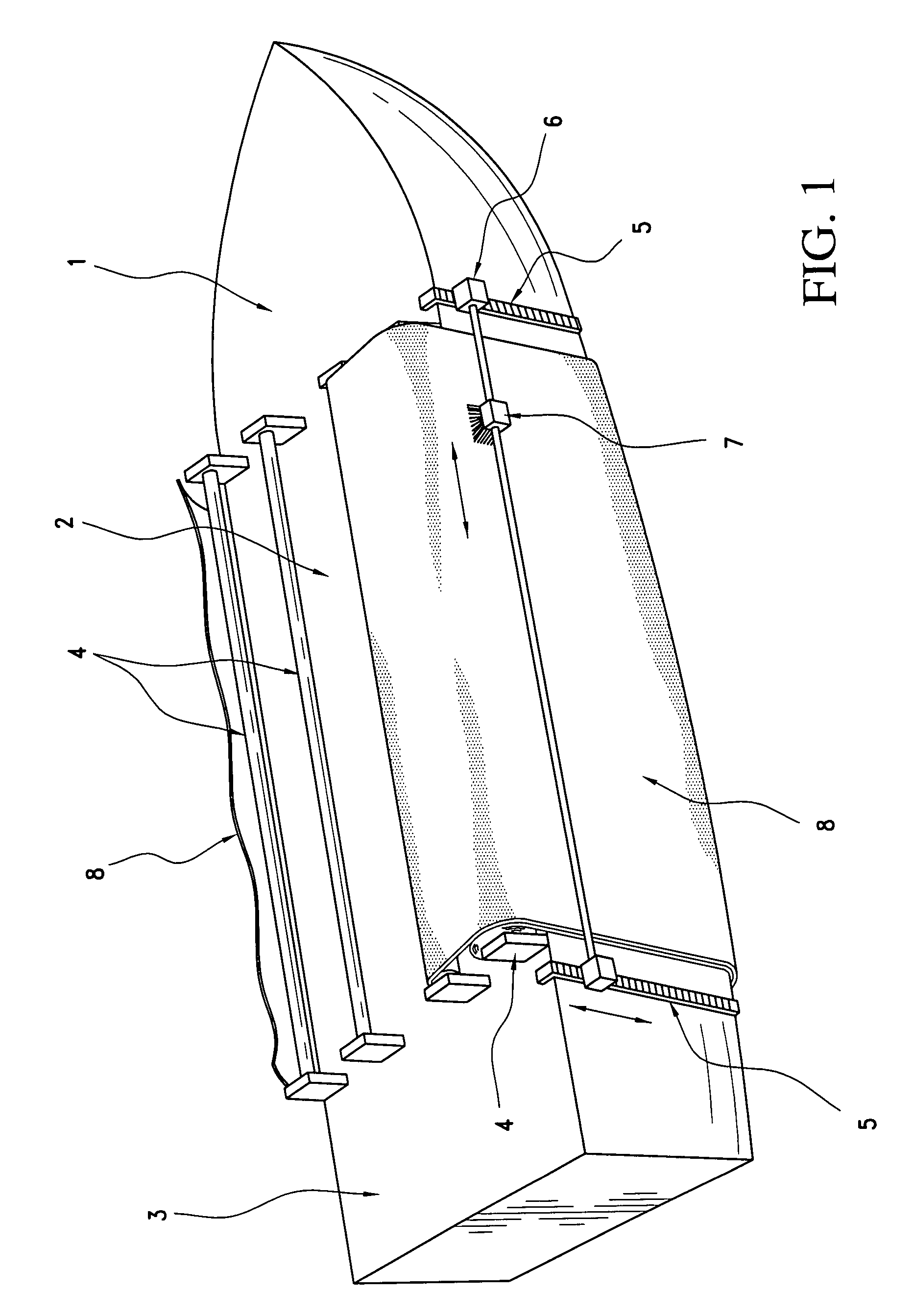
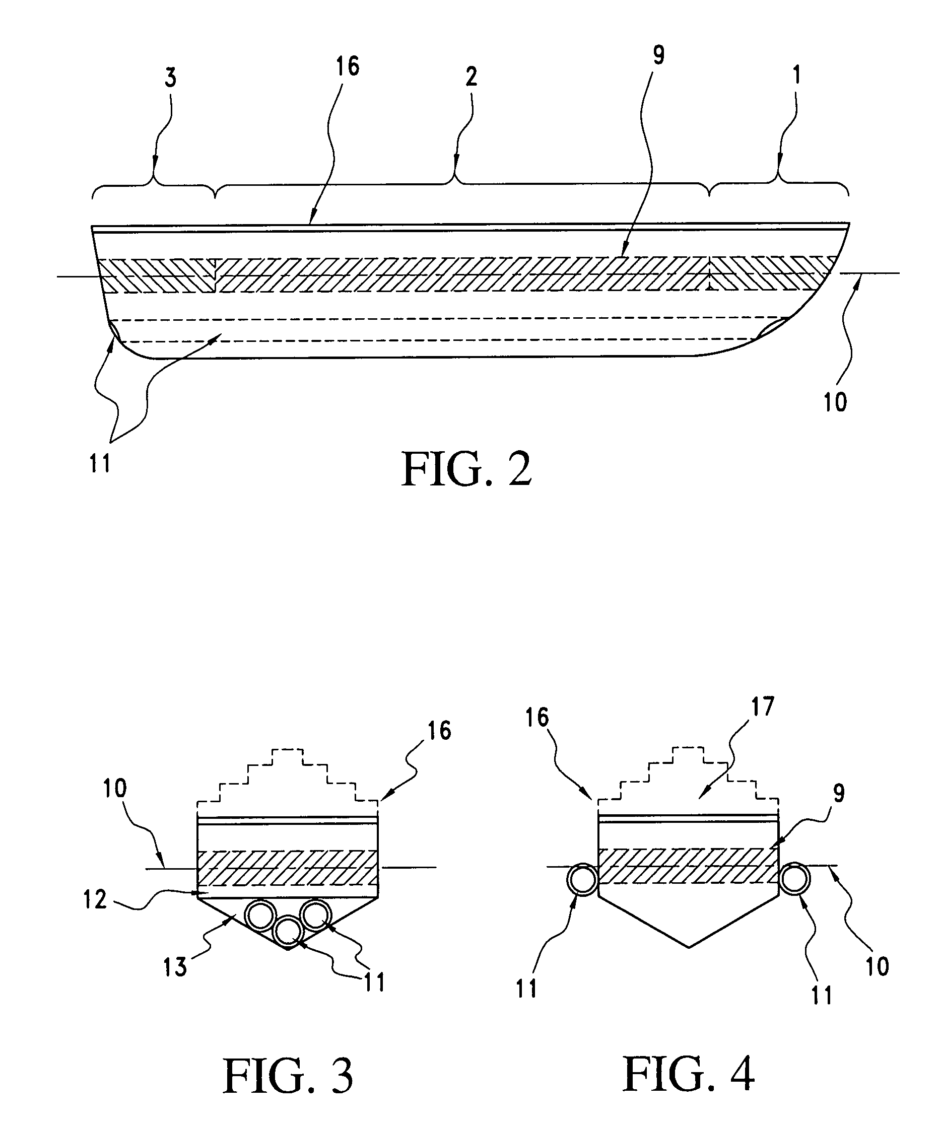
[0030]The present invention provides for more rapid self-repair of hull damage through the use of a double sheath construct of water impermeable material. Each sheath can be rotated in a direction opposite to the other in order to provide two layers of undamaged sheath material to cover and seal any damaged area while more permanent repairs are made. The sheaths may be made of any flexible and easily handling material such as certain rubbers e.g. fiber or steel reinforced rubbers, sealed foams, and resilient metal foils. They are thin enough to be rolled onto spindles for storage and for use. It is envisioned that sheaths for typical use will range from about one half to two inches in thickness. Lightweight materials are preferred for ease of transport and ease of rolling onto the axles or spindles.
[0031]In one embodiment, the sheaths are mounted on spindles at each end above the waterline. While these spindles can be mounted on the main deck, it is often preferable to have them mou...
PUM
 Abstract
Description
Claims
Application Information