
Optical near-field generator and near-field optical recording and reproduction apparatus

a generator and optical recording technology, applied in special recording techniques, instruments, nanoinformatics, etc., can solve problems such as energy loss and efficiency reduction, and achieve the effect of preventing the reduction of optical near-field intensity

Inactive Publication Date: 2008-04-15
HITACHI LTD
View PDF8 Cites 23 Cited by
  • Summary
  • Abstract
  • Description
  • Claims
  • Application Information

AI Technical Summary

Benefits of technology

The invention aims to improve the efficiency of producing optical near-field by minimizing the spot size of the incident light on the scatterer. This is achieved by guiding the light to the scatterer through a waveguide or condenser lens and covering the portions near the scatterer with a material having a smaller refractive index. However, this can cause a reduction in the intensity of the optical near-field due to polarization. To address this, the invention proposes using a scatterer with a planar-triangular shape and a low refractive index material covering the portions near the scatterer. This reduces the magnitude of polarization and increases the intensity of the optical near-field. The invention also suggests using a scatterer with a low refractive index material having a smaller thickness than the waveguide core to minimize reflected light and increase the intensity of the optical near-field. Additionally, the invention proposes using a scatterer with a low refractive index material having a smaller refractive index than the lens to prevent a decrease in the optical near-field intensity.

Problems solved by technology

Such passing light leads to energy loss and reduced efficiency.
However, when the scatterer is formed in a high refractive index material, a large polarization is caused in the high refractive index material, and it to cancel the effect of the charges collecting on the surface of the metal scatterer.

Method used


Image

  • Optical near-field generator and near-field optical recording and reproduction apparatus
  • Optical near-field generator and near-field optical recording and reproduction apparatus
  • Optical near-field generator and near-field optical recording and reproduction apparatus

Examples


example 1

[0033]Initially, a case where a waveguide is used as a means to transmit incident light to a optical near-field element is described.

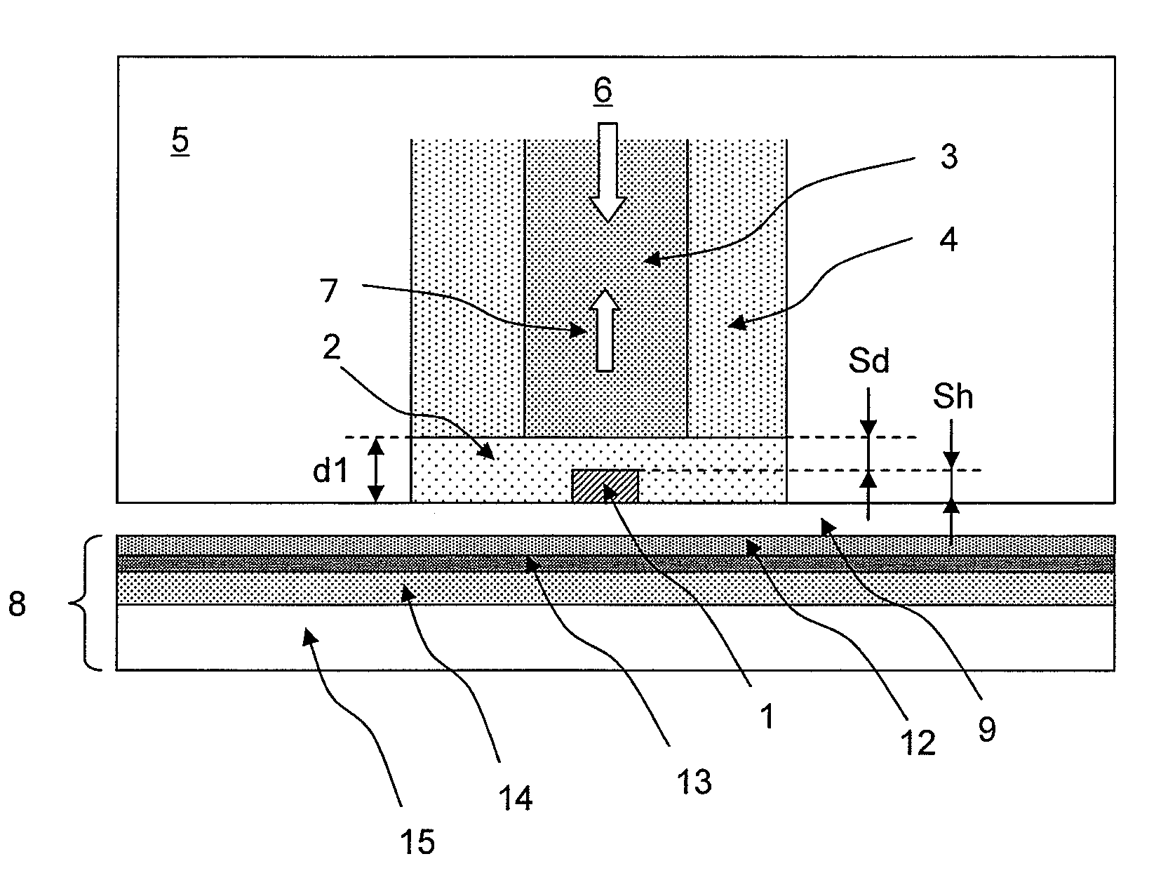
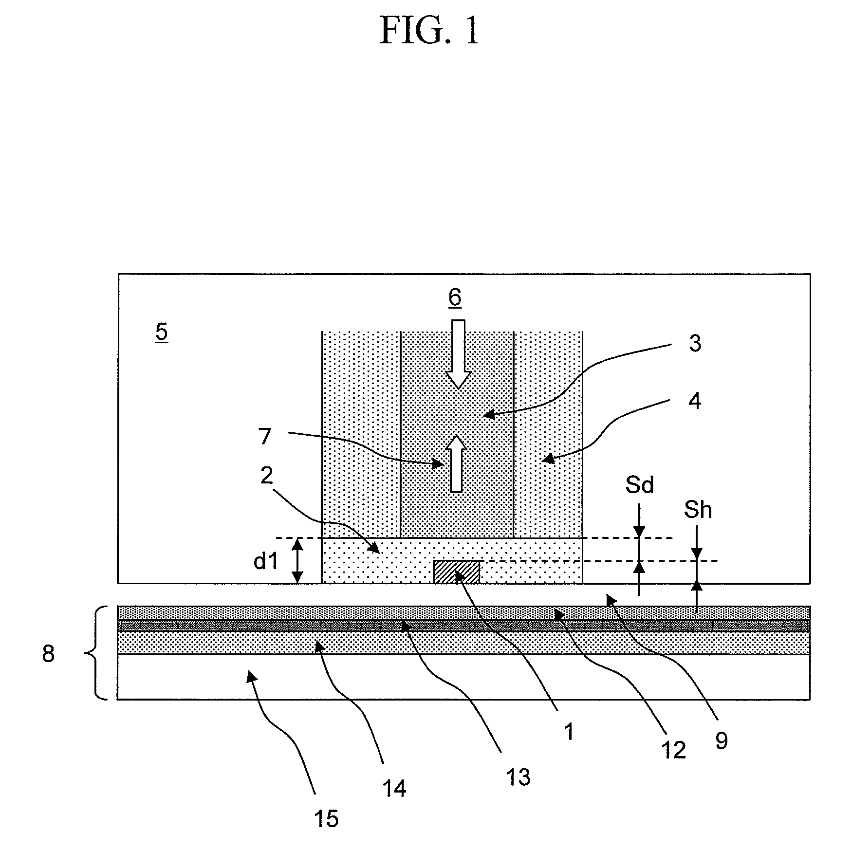
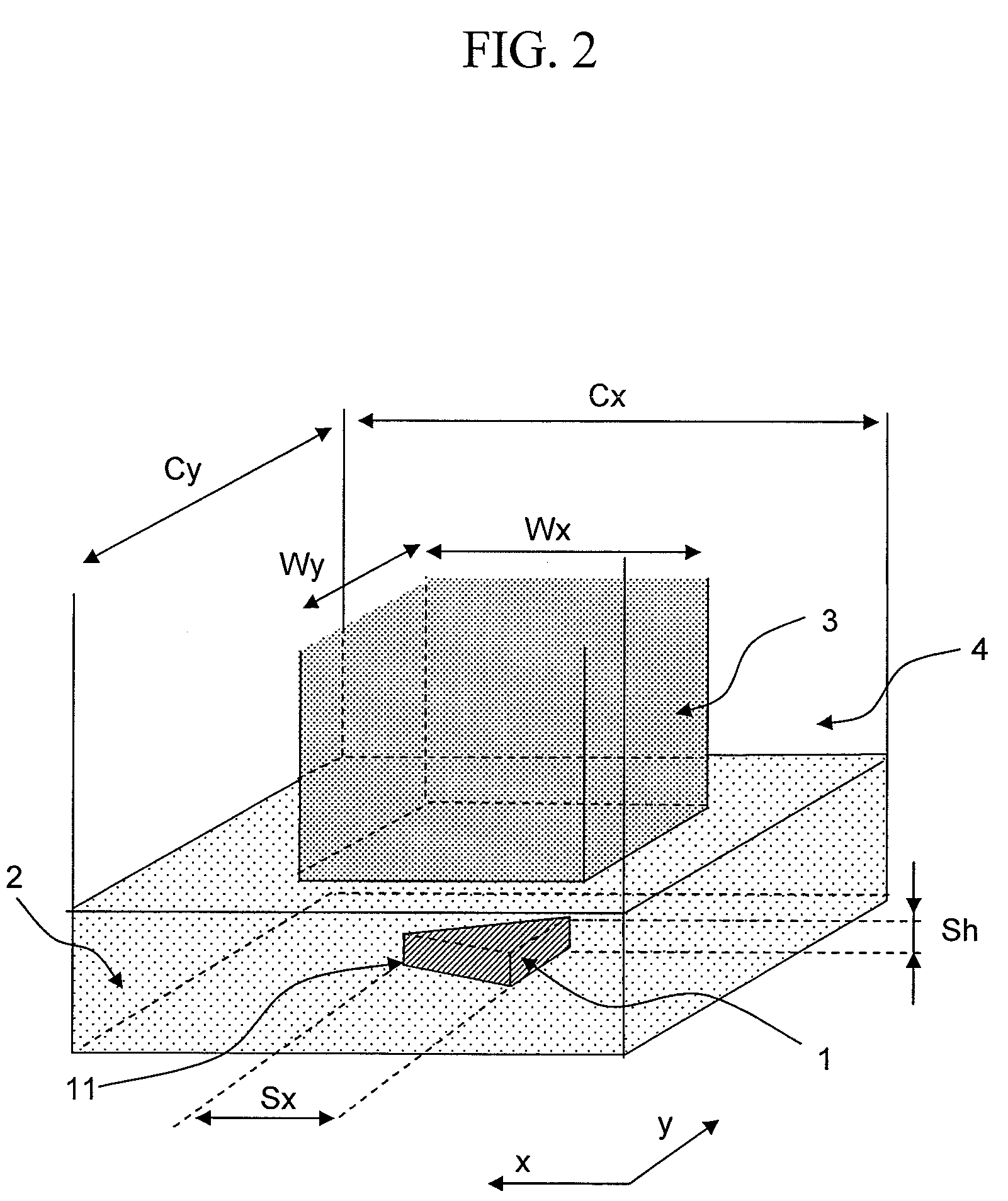
[0034]FIGS. 1 and 2 show an example of a head for a thermally assisted magnetic recording apparatus using a waveguide. In a slider 5, which constitutes a base for the head, a waveguide (composed of a core 3 and a cladding 4) for guiding light to a optical near-field generating element was formed. Below the waveguide, a scatterer 1 for producing optical near-field was formed. The material of the core 3 of the waveguide was Ta2O5 (refractive index=2.18), and the material of the cladding was SiO2. The waveguide had a square cross-section, with its widths Wx and Wy both measuring 500 nm. The cladding also had a square cross-section, with the widths Cx and Cy both measuring 1.0 μm.

[0035]As shown in FIG. 2, the scatterer 1 had a planar triangular shape, and its material was gold. The length Sx was 100 nm; thickness Sh was 50 nm; and the apex angle of an apex...

example 2

[0056]In the following, an example is described in which a lens is used as the means to transmit the incident light to the optical near-field element.

[0057]FIG. 11 shows the example in which a lens is used. In the present example, the lens consisted of a hemispheric lens 16 made of Bi4Ge3O12 (refractive index=2.23). The lens 16 was formed on the bottom surface of the slider 5, and the incident light 6 was caused to become incident on the lens such that the light is collected at the bottom surface of the hemispheric lens. The scatterer 1 was formed at the focal position on the bottom surface of the lens. The shape and material of the scatterer were the same as in the foregoing example. Around the scatterer 1, a hemispheric low refractive index portion 2 was formed of SiO2. It is necessary to reduce the thickness d1 of the low refractive index portion 2 but only to such an extent that the light-collecting characteristics of the lens do not deteriorate. For that purpose, the thickness ...

example 3

[0059]In the following, an example is described in which the optical near-field generator of the invention is combined with a single-pole head that is used in magnetic disc drives.

[0060]FIG. 13 shows a cross section of a recording head combining a single-pole head and a scatterer. On the surface of the slider 5, the scatterer 1 for producing optical near-field was formed, around which the low refractive index portion 2 was formed. Light was produced by a semiconductor laser with a wavelength 785 nm. The light emitted by the semiconductor laser was guided via a waveguide 22 to the slider 5. The light emerging from the waveguide 22 was collimated into parallel light by collimating lens 23. The light was folded by a mirror 24 and then coupled to a waveguide (consisting of a core 3 and a cladding 4) via a condenser lens 25, the waveguide connecting to the optical near-field generating element. A magnetic field was produced by a thin-film coil 17 and guided by a main magnetic pole 18 to ...


PUM

PropertyMeasurementUnit
widths Wxaaaaaaaaaa
widthsaaaaaaaaaa
length Sxaaaaaaaaaa

Abstract

Decrease in optical near-field intensity is prevented when an light propagating medium made of a high refractive index material, such as a waveguide or a lens, is combined with a scatterer for producing optical near-field. Near the optical near-field generating element, a second light propagating medium is disposed in contact with a first light propagating medium of a high refractive index material, such as a waveguide or a lens. The refractive index of the second light propagating medium is made smaller than the refractive index of the first light propagating medium.

Description

CLAIM OF PRIORITY[0001]The present application claims priority from Japanese application JP2006-109389 filed on Apr. 12, 2006, the content of which is hereby incorporated by reference into this application.BACKGROUND OF THE INVENTION[0002]1. Field of the Invention[0003]The present invention relates to a optical near-field generator and a near-field optical recording and reproduction apparatus having a optical near-field generator mounted in a head thereof.[0004]2. Background Art[0005]In recent years, a thermally assisted magnetic recording has been proposed as a means of realizing high recording densities of 1 Tb / in2 or greater (H. Saga, H. Nemoto, H. Sukeda, and M. Takahashi, Jpn. J. Appl. Phys. 38, Part 1, 1839 (1999)). In conventional magnetic recording apparatuses, there is the problem of loss of recorded information due to heat fluctuation as the recording density exceeds 1Tb / in2. In order to prevent this problem, it is necessary to increase the coercive force of the magnetic r...

Claims


Application Information

Patent Timeline
Patent Type & Authority Patents(United States)
IPC IPC(8): G02B6/42G02B6/30G02F1/295G01Q60/18G01Q60/22G01Q80/00G11B5/02G11B7/135
CPCB82Y20/00B82Y35/00G01Q60/22G11B5/314G11B7/124G11B7/1387G11B5/02B82Y10/00G01Q80/00G11B2005/0021G11B2005/0002
Inventor MATSUMOTO, TAKUYA
Owner HITACHI LTD
Learn More