
Methods, architectures, circuits, software and systems for CRC determination

a technology of architecture and circuit, applied in the field of data transmission error determination, can solve the problems of inefficient approach of fig. 2a-2b in terms of circuit use and/or chip area, architectures also unnecessarily consume power to keep all of the crc circuitry active, etc., to achieve the effect of improving operational and functional circuit area efficiencies, increasing network speeds, and increasing calculation speed

Active Publication Date: 2008-04-15
MARVELL ISRAEL MISL
View PDF44 Cites 43 Cited by
  • Summary
  • Abstract
  • Description
  • Claims
  • Application Information

AI Technical Summary

Benefits of technology

[0013]The present invention advantageously provides CRC circuitry and a CRC architecture with (i) increased calculation speed and (ii) improved operational and functional circuit area efficiencies, thereby providing increased network speeds, smaller chip and IC package sizes, and reduced power consumption, thereby enabling smaller board designs and reduced power consumption and heat generation in systems containing circuitry implementing the present invention.

Problems solved by technology

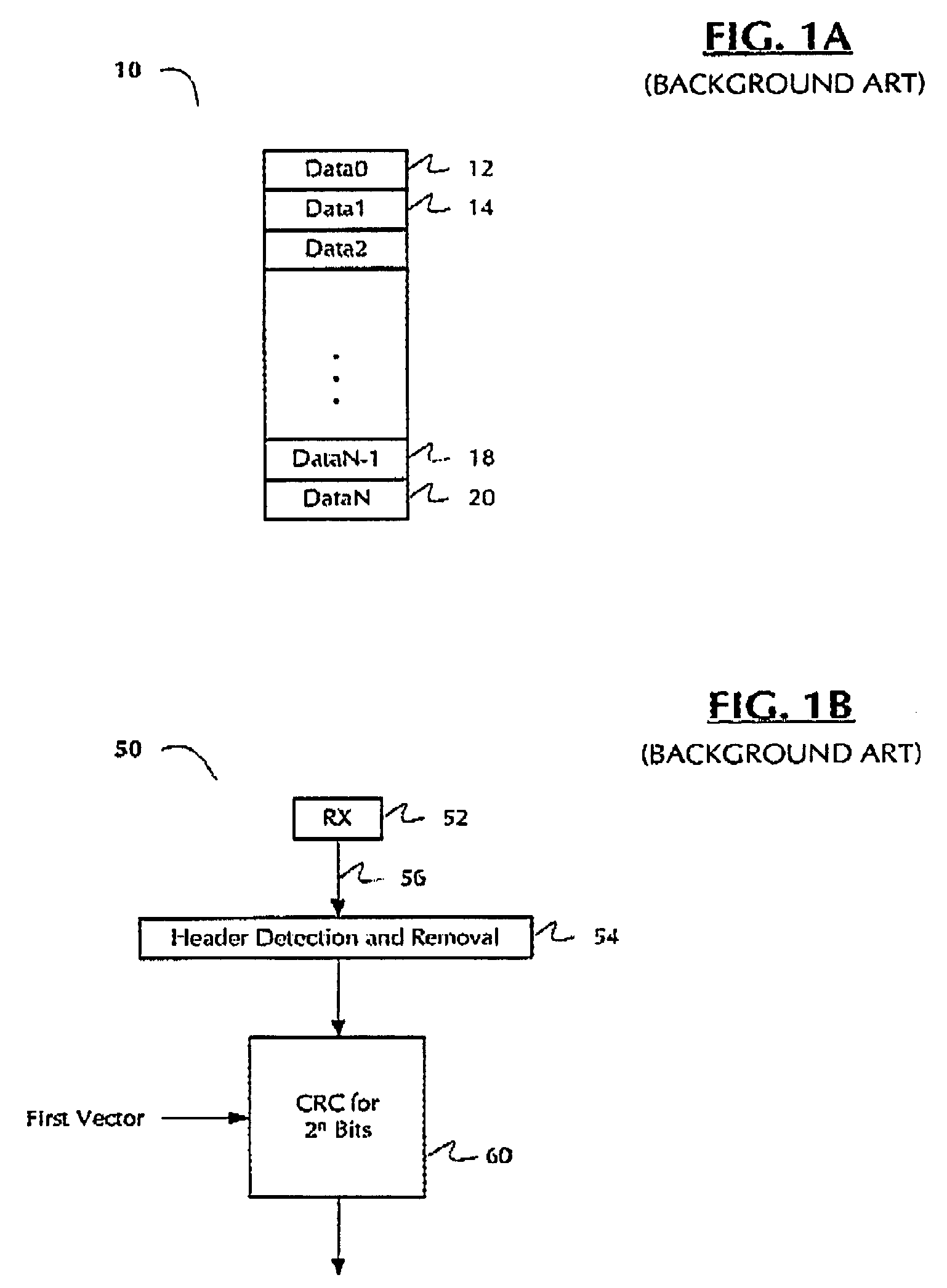
The approach becomes more complicated when the packet contains a number of data bits that is not an integer multiple of the CRC calculating circuitry width.
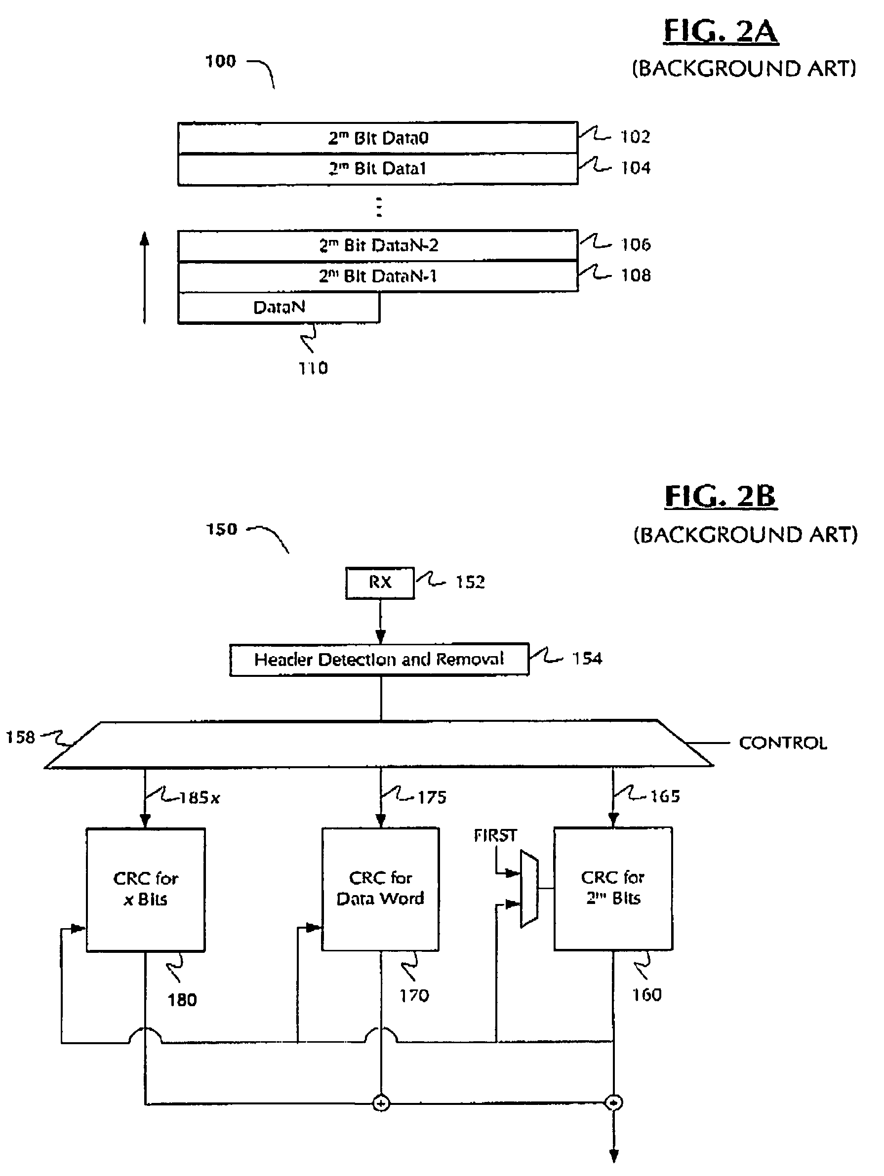
While providing some improvement over the approach of FIGS. 1A-1B in calculation time, the approach of FIGS. 2A-2B is inefficient in terms of circuit use and / or chip area.
Such architectures also unnecessarily consume power to keep all of the CRC circuitry active, even when it is not in use.
In many cases, some bus lengths to and from second, third and / or further CRC blocks are relatively long, and thus consume incrementally greater power when transmitting data or even staying active, in comparison with the main (e.g., 2m bit) CRC block.

Method used


Image

  • Methods, architectures, circuits, software and systems for CRC determination
  • Methods, architectures, circuits, software and systems for CRC determination
  • Methods, architectures, circuits, software and systems for CRC determination

Examples


Embodiment Construction

[0026]Reference will now be made in detail to the preferred embodiments of the invention, examples of which are illustrated in the accompanying drawings. While the invention will be described in conjunction with the preferred embodiments, it will be understood that they are not intended to limit the invention to these embodiments. On the contrary, the invention is intended to cover alternatives, modifications and equivalents, which may be included within the spirit and scope of the invention as defined by the appended claims. Furthermore, in the following detailed description of the present invention, numerous specific details are set forth in order to provide a thorough understanding of the present invention. However, it will be readily apparent to one skilled in the art that the present invention may be practiced without these specific details. In other instances, well-known methods, procedures, components, and circuits have not been described in detail so as not to unnecessarily ...


PUM


Abstract

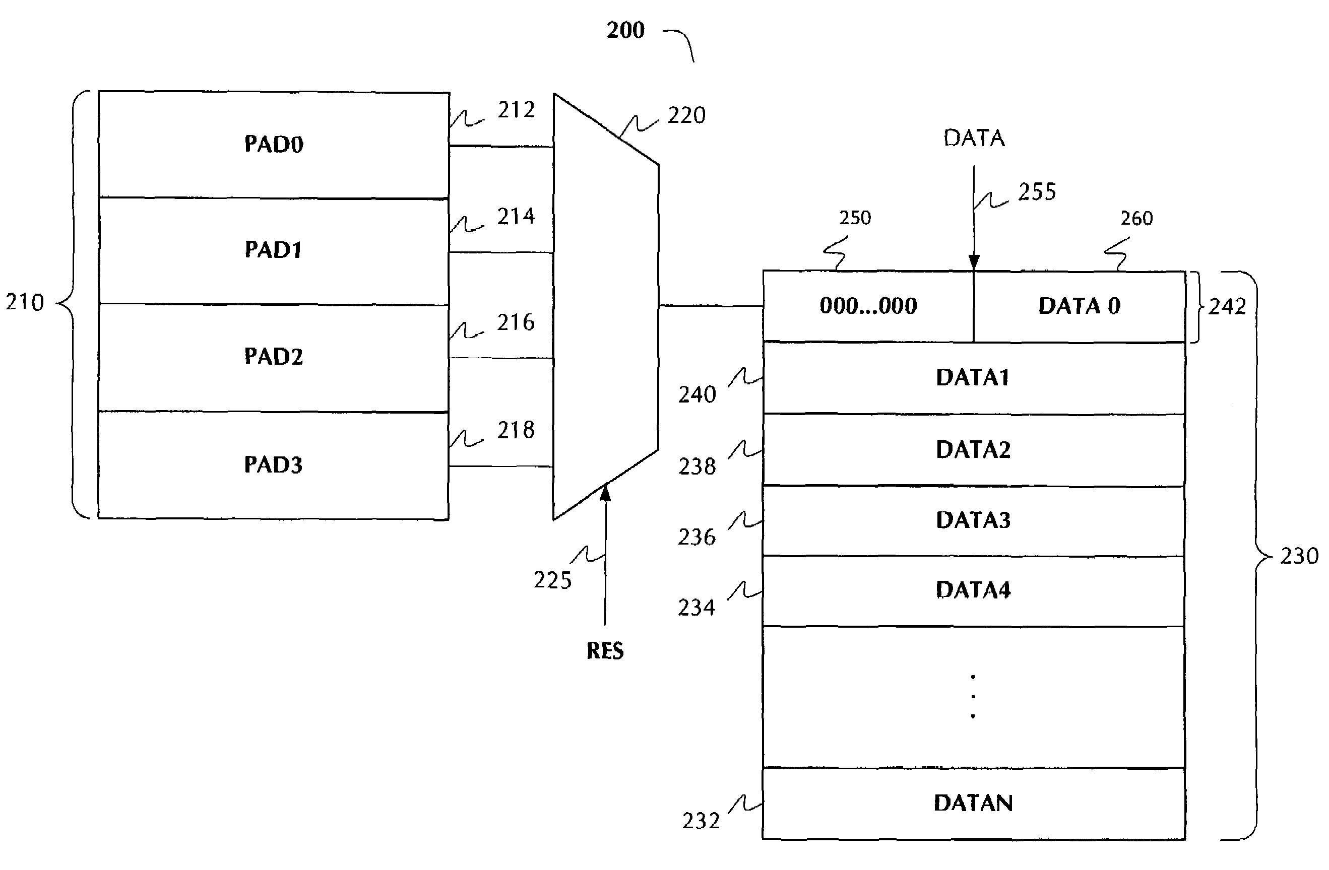
Methods, circuits, architectures, and systems for error detection in transmitted data. The method generally includes the steps of (i) partitioning the unit of digital data into one or more full data lines and a remainder, wherein each of the full data lines comprises a predetermined number of data blocks, each of the data blocks has a first fixed length, the predetermined number is an integer of at least 2, and the remainder has a length less than the predetermined number times the first fixed length; (ii) if the remainder contains at least one data bit, adding to the remainder a padding vector having a length sufficient to generate a padded data line having the predetermined number of data blocks; and (iii) performing error checking calculations on the full data lines and the padded data line. The present invention reduces the chip area and power consumption, while improving system performance.

Description

RELATED APPLICATION(S)[0001]The present application may be related to the co-pending, commonly-owned applications entitled “Methods, Architectures, Circuits, and Systems for Transmission Error Determination” (Ser. No. 10 / 690,780, filed on Oct. 21, 2003) and / or “Method(s), Architecture(s), Circuits, and Systems for Checking Error Determinations” (Ser. No. 10 / 795,003, filed on Mar. 3, 2004), the disclosures of which are incorporated herein by reference in their entireties.FIELD OF THE INVENTION[0002]The present invention generally relates to the field of data transmission error determinations. More specifically, embodiments of the present invention pertain to methods, architectures, circuits, software and systems for cyclic redundancy checking (“CRC”) in a data storage or communications network.DISCUSSION OF THE BACKGROUND[0003]CRC is a well-known, conventional technique for finding data transmission errors. Typically, CRC is performed “on-the-fly” by hardware or logic circuitry, usua...

Claims


Application Information

Patent Timeline
IPC IPC(8): H03M13/00
CPCH03M13/09H03M13/6516
Inventor BARASH, DROR
Owner MARVELL ISRAEL MISL
Learn More