Method and apparatus for rebound control

a rebound control and apparatus technology, applied in mechanical apparatus, shock absorbers, transportation and packaging, etc., can solve problems such as increased body roll, and achieve the effect of reducing momentum or inertial weight gain and eliminating as much roll

Inactive Publication Date: 2008-04-22
AMTECH
View PDF15 Cites 18 Cited by
  • Summary
  • Abstract
  • Description
  • Claims
  • Application Information

AI Technical Summary

Benefits of technology

[0027]The solution, as disclosed herein, may include an added rebound spring mounted coaxial about the shock absorber tube to act primarily to resist rebound of the suspension from the design height position and thereby apply resistive force to the chassis via the shock absorber to reduce lift. The coil rebound spring can also be added to a strut type suspension for exactly the same purpose. It is an advantage of the present invention that it can be easily and inexpensively added as an after market supplement to either the front or rear of an existing vehicle suspension with tubular shock absorbers. It is a further advantage of the present invention that the coil rebound spring has very little influence on ride height and / or ride stiffness.
[0028]The coil rebound spring works from one inch of jounce travel all the way to full rebound travel of the shock absorber. It works to prevent the onset of roll from the design height, rather than limiting the roll to a certain amount after it has rolled a certain amount. Limiting the roll from the design height position serves to reduce the momentum or inertial weight gain that occurs at the initiation of roll and continues after roll has begun. In other words, we seek to eliminate as much roll as possible from the outset. Rebound control overlaps the jounce control; therefore the disclosed system is truly bi-linear, a preferred embodiment.

Problems solved by technology

The transitory effects of body roll during cornering flex the load springs on the side of the vehicle following the outside of the turn due to increased transfer weight to that side.
Meanwhile the springs on the side of the vehicle, following the inside of the turn, unload extending toward their free position using the axle as a location for inducing lift of the sprung weight on that side resulting in increased body roll.

Method used


Image

  • Method and apparatus for rebound control
  • Method and apparatus for rebound control
  • Method and apparatus for rebound control

Examples


Embodiment Construction

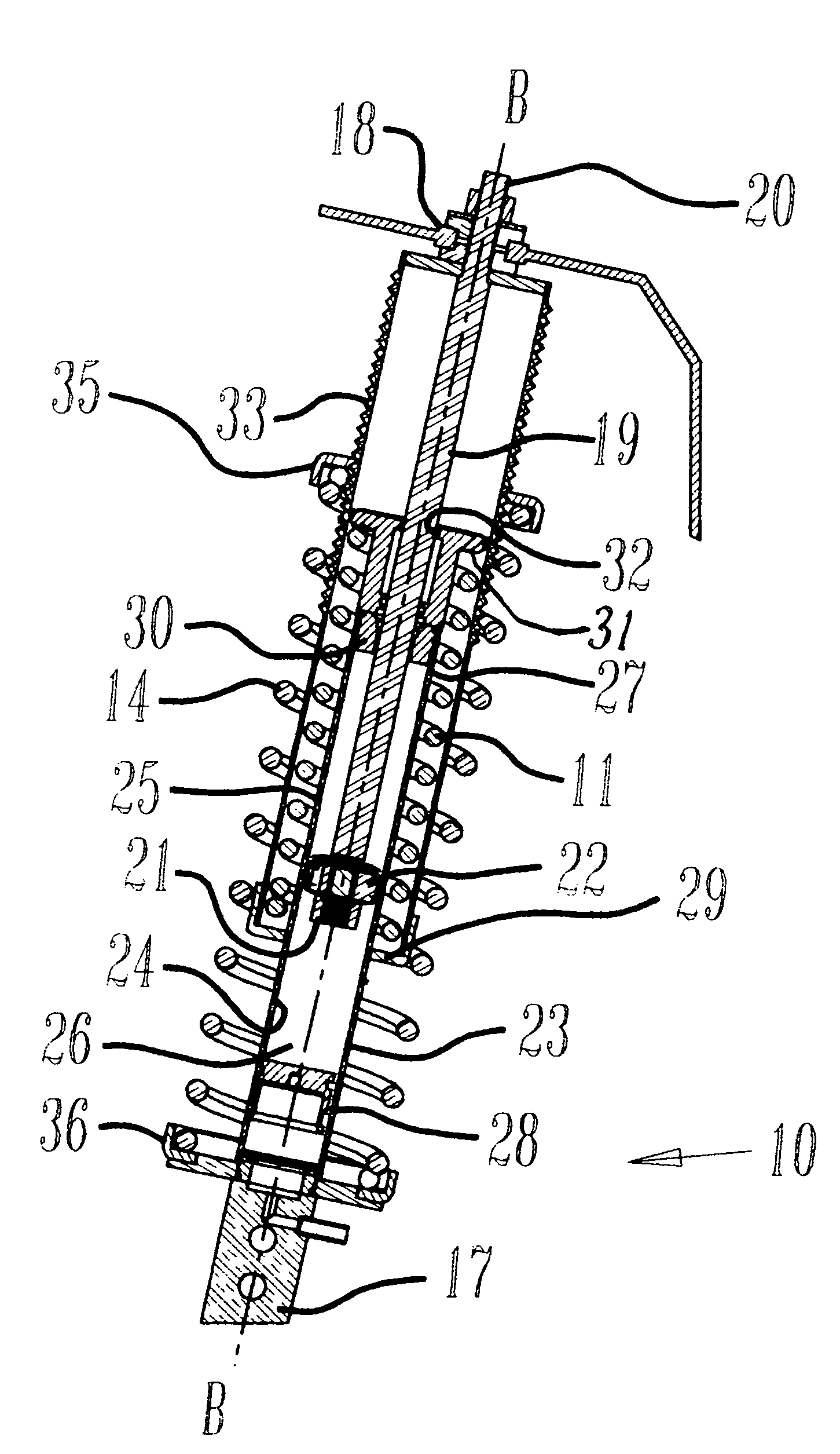
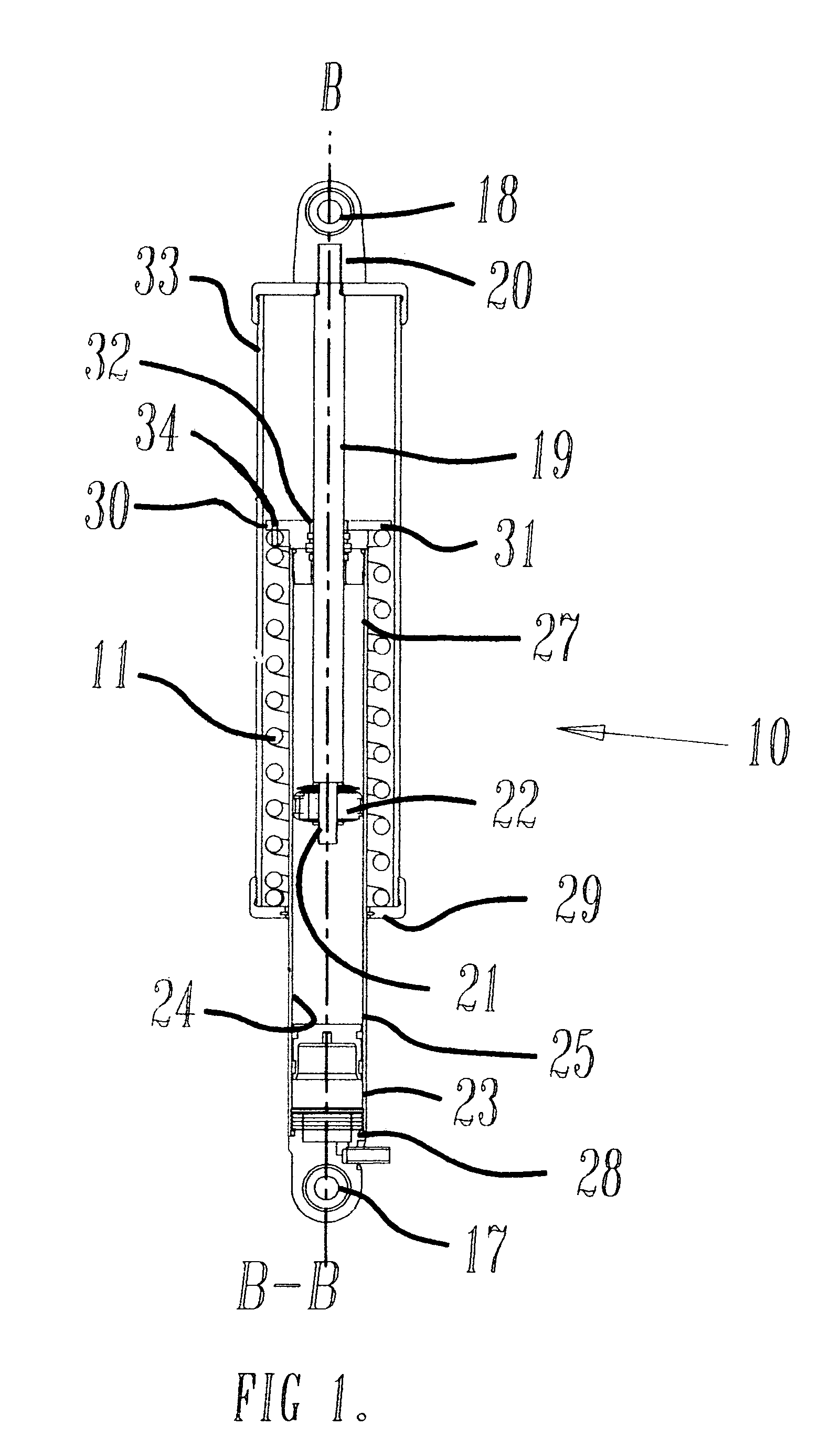
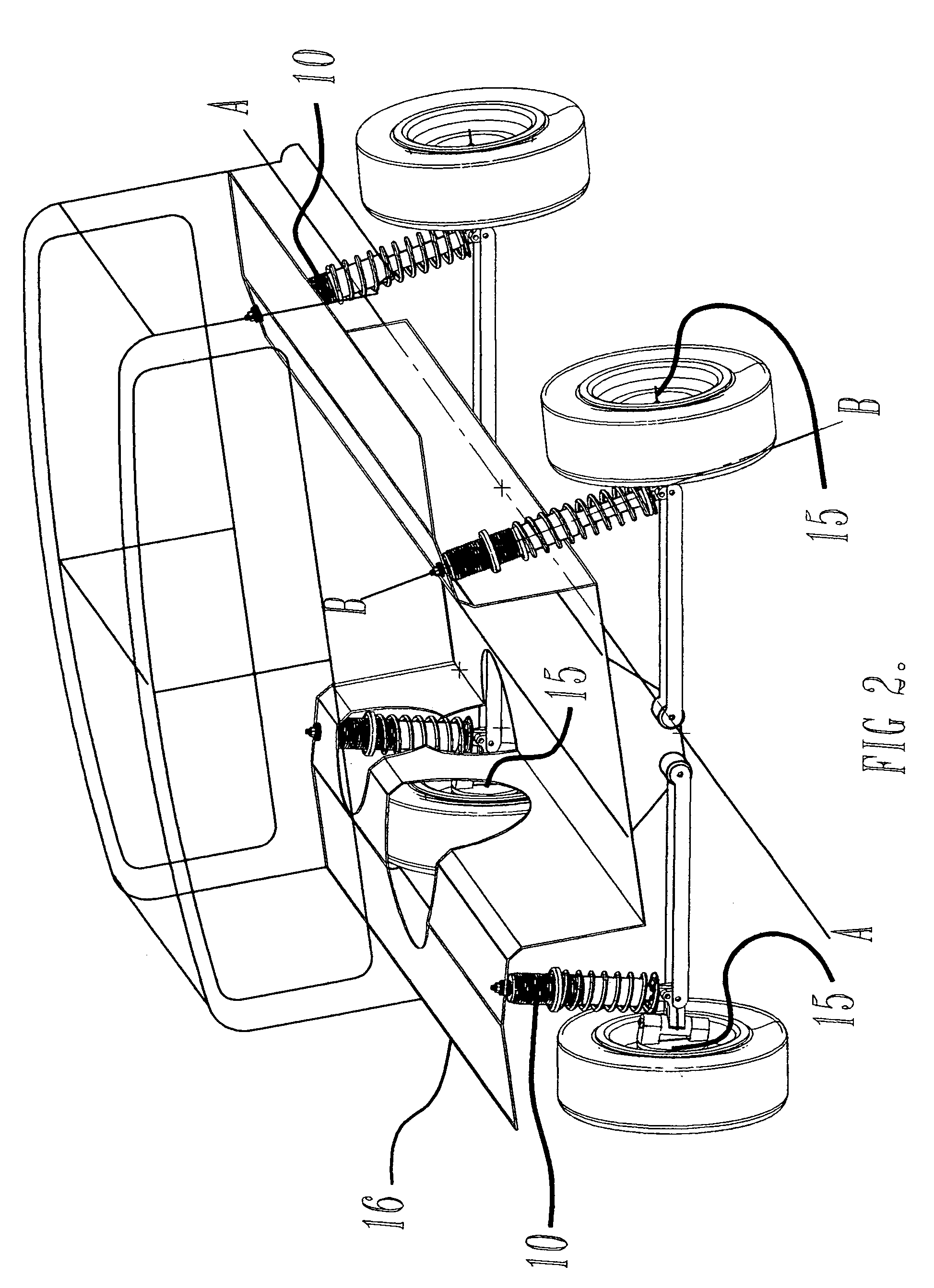
[0033]FIG. 1 shows a cross section view of a vehicle rebound control shock absorber 10 with a special suspension coil rebound spring 11 arrangement. It is to be used to replace a standard shock absorber installation independent of the vehicle spring system, as is commonly found in both vehicles with leaf type and coil type suspension spring systems. Commonly a shock absorber connects the sprung mass to the un-sprung mass and is used only to dampen unsprung mass oscillations induced by bumpy roads and sometimes with helper load springs for preloaded height and jounce improvement. The sprung mass is carried on vehicle chassis and body and herein after will be referred to structurally as chassis 16. The unsprung weight is that which is not supported by the vehicle suspension spring system, i.e. axles 15, wheels, tires, brake assemblies and suspension components that hang downwardly if the body is lifted. Typically, the passenger vehicle has four wheels with associated suspension with t...


PUM


Abstract

A stabilizing apparatus and method that replaces the existing shock absorber of a road vehicle that works to resist the initiation of body roll during cornering. It seeks to counter act the forces being generated by the vehicle suspension springs that exacerbate the rollover propensity of vehicles during certain steering maneuvers.

Description

CROSS REFERENCE TO RELATED APPLICATIONS[0001]This application is related to:[0002]U.S. Ser. No. 09 / 803,505 filed on Mar. 9, 2001 entitled: Opposing Spring Resilient Tension Suspension System.[0003]U.S. Ser. No. 10 / 033,016 filed on Oct. 26, 2001 entitled: Opposing Spring Rebound Tension Suspension System.[0004]U.S. Ser. No. 10 / 100,313 filed on Mar. 16, 2002 entitled: Method and Apparatus for Rebound Control.STATEMENT REGARDING FEDERALLY SPONSORED RESEARCH OR DEVELOPMENT[0005]Not ApplicableREFERENCE TO A “MICROFICHE APPENDIX”[0006]Not ApplicableBACKGROUND OF THE INVENTION[0007]1. Field of the Invention[0008]The present invention relates to and, in particular, to improvements in the methods and apparatus for using a rebound spring carried on a shock absorber that is intended to utilize the unsprung weight of the wheel / axle system during rebound. More particularly, it is to resist rollover, sway, yaw and other chassis motion.[0009]2. Description of Related Art Including Information Disc...

Claims


Application Information

Patent Timeline
Patent Type & Authority Patents(United States)
IPC IPC(8): B60G3/26B60G13/00B60G3/20B60G15/06F16F13/00
CPCB60G15/06B60G17/021F16F13/007B60G2500/20
Inventor BRYANT, PETER E.
Owner AMTECH
Why Eureka
Try Eureka