Filter function-equipped optical sensor and flame sensor

a filter device and optical sensor technology, applied in the field of photosensors and flame sensors, can solve the problems of cracks, narrow wavelength ranges, and inability to fully obtain the above-described sensitivity difference, and achieve the effect of high resistance (environmental resistance) and effective detection

Active Publication Date: 2008-04-22
SOKO KAGAKU
View PDF13 Cites 33 Cited by
  • Summary
  • Abstract
  • Description
  • Claims
  • Application Information

AI Technical Summary

Benefits of technology

[0017]Namely, according to this first characterizing feature, the filter device includes a colored glass filter and the first interference filter structure described above and the light receiving device is comprised of a semiconductor photodetector structure having a light receiving area which contains InAlGaN. Hence, there is provided a photosensor constructed such that the light irradiated on the photosensor from the outside will reach the light receiving device with its light components of the longer wavelength range than the detection target wavelength range being effectively shielded by the filter device and the light of other wavelength range than the detection target wavelength range is prevented from reaching the light receiving area of the light receiving device. Further, since InAlGaN is a direct transition type semiconductor, the light absorption spectrum of the light receiving area sharply varies at the absorption end wavelength, so that there is provided a photosensor having good wavelength selectivity.
[0035]Namely, with this characterizing feature, since the flame sensor is formed by sealing the photosensor having a filter function with nitrogen gas or inert gas, it is possible to provide a flame sensor having high resistance (environmental resistance) against heat, moisture, etc. Further, by combing the above-described filter device with the above-described light receiving device, there is obtained a flame sensor providing a large sensitivity difference between the sensitivity for the detection target wavelength range (the range including the flame light) and the sensitivity for the non-detection target wavelength ranges (the ranges including external disturbance light such as sunlight, room light, etc.). As a result, it is possible to provide a flame sensor capable of effectively detecting even weak light within the detection target wavelength range.

Problems solved by technology

Hence, the above-described sensitivity difference cannot be fully obtained.
However, since the interference filter structure shields the light of predetermined wavelength range through the light interference function, the wavelength range which can be shielded by the filter device is very narrow.
However, it has been found that with thick deposition of interference filter structures, there occurs a new problem of cracks therein.
Further, the state-of-the art filters designed for selectively transmitting UV-B or UV-C alone suffer poor wavelength selectivity in permitting good transmission of light of a detection target wavelength while effectively shielding lights of non-target wavelengths.
For this reason, it has been impossible to detect, with high precision, UV-B or UV-C contained in the sunlight and having a very weak light intensity And, there is another problem that due to emission of line spectra from the mercury lamp other than the desired line spectrum, integrated sensitivities for the longer wavelength side of the light receiving device are inadvertently added to the output of the illuminometer.
In addition, substantially no colored glass filter is presently available which is capable of good transmission of the ultraviolet light.
Therefore, it is known that such colored glass filter suffers the problem of occurrence of undesirable change in its optical characteristics due to environmental influence such as heat or moisture.
Especially, if a filter device using the colored glass filter is combined with a light receiving device to construct a photosensor expected to selectively detect light of a predetermined wavelength range alone as described above, such change with time in the optical characteristics of the colored glass filter (namely change in wavelength / intensity of the light incident on the light receiving device) will be a serious problem.
As a result, the result of flame light detection by such flame sensor (photosensor) will be unreliable.

Method used


Image

  • Filter function-equipped optical sensor and flame sensor
  • Filter function-equipped optical sensor and flame sensor
  • Filter function-equipped optical sensor and flame sensor

Examples


Embodiment Construction

[0047]A photosensor relating to the present invention will be described with reference to the accompanying drawings.

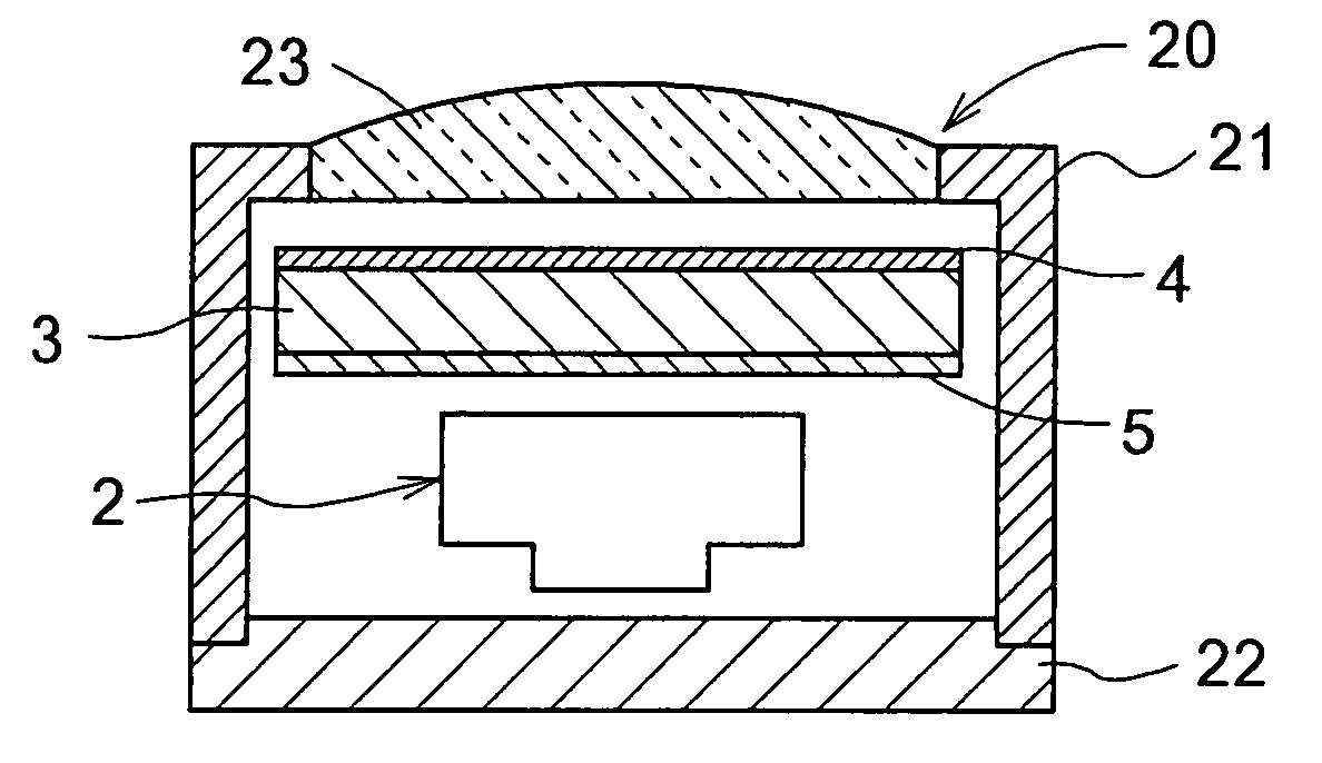
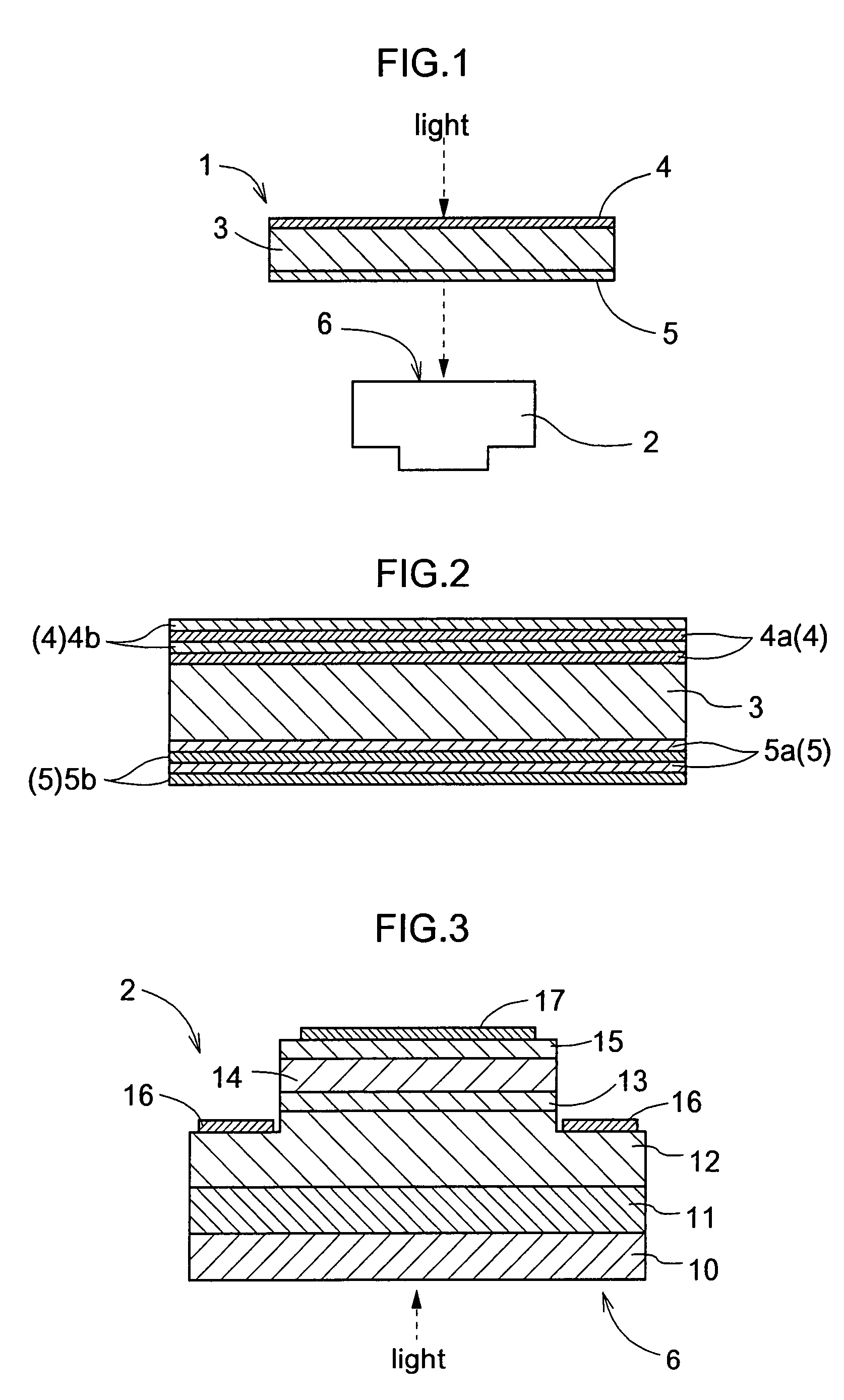
[0048]FIGS. 1 through 3 illustrate a construction of a photosensor including a filter device 1 and a light receiving device 2. The filter device 1 comprises a colored glass filter 3 and a first interference filter structure 4 deposited on at least one face of the filter 3, the first interference filter structure 4 being comprised of a plurality of light transmitting layers 4a, 4b stacked on each other and configured to be capable of shielding light of a predetermined first wavelength range. Further, the photosensor illustrated in FIG. 1 and FIG. 2 includes also a second interference filter structure 5 deposited on the other face of the colored glass filter 3 than the one face on which the first interference filter structure 4 is deposited, the second interference filter structure 5 being comprised of a plurality of light transmitting layers 5a, 5b and configured to be ...


PUM


Abstract

In order to provide a filter device capable of maintaining stable optical characteristics for an extended period of time and to provide also a photosensor using the filter device, a photosensor having a filter function includes a filter device having a colored glass filter and configured for permitting transmission of light of a predetermined wavelength range including a detection target wavelength range and a light receiving device for receiving the light transmitted through the filter device. The filter device includes a first interference filter structure comprised of a plurality of light transmitting layers stacked on each other, the first interference filter structure being deposited on a face of the colored glass filter. The light receiving device includes a semiconductor photodetector structure having one or more semiconductor layers, a light receiving area being formed in the one or more semiconductor layers within the semiconductor photodetector structure. The one or more semiconductor layers forming the semiconductor photodetector structure contain InxAlyGa1-x-yN (0≦x≦0.21, 0≦y≦1).

Description

BACKGROUND OF THE INVENTION[0001]1. Field of the Invention[0002]The present invention relates to a photosensor and a flame sensor including a filter device provided on a light incident face of a light receiving device, the filter device comprising an interference filter structure deposited on a colored glass filter.[0003]2. Description of Related Art[0004]Conventionally, there has been proposed a photosensor made by first preparing a colored glass filter by adding a color coupler (metal or metal compound) to glass and then assembling this colored glass filter with a light receiving device. This photosensor is configured such that light of a predetermined wavelength range is cut off by the colored glass filter and light of a desired wavelength range passing the colored glass filter is detected (see e.g. FIG. 1 of Japanese Patent Application “Kokai” No. 11-153483). For instance, for selectively detecting ultraviolet light contained in sunlight ranging from the ultraviolet range to the...

Claims


Application Information

Patent Timeline
Patent Type & Authority Patents(United States)
IPC IPC(8): H01L31/062H01L27/14G02B5/28H01L27/144H01L27/146H01L31/0232H01L31/10
CPCG02B5/284
Inventor HIRANO, AKIRAKAMIYAMA, SATOSHIAMANO, HIROSHIAKASAKI, ISAMU
Owner SOKO KAGAKU
Why Eureka
Try Eureka