
Jet orifice plate with projecting jet orifice structures for direct impingement cooling apparatus

a technology of direct impingement and jet orifice plate, which is applied in the direction of cooling/ventilation/heating modification, lighting and heating apparatus, semiconductor devices, etc., can solve the problems of high heat load, electronic and mechanical failures that will affect the overall system performance, and device performance challenges, so as to facilitate the removal of coolant effluent and reduce the pressure drop across the jet orifice plate

Inactive Publication Date: 2008-04-22
INT BUSINESS MASCH CORP
View PDF22 Cites 66 Cited by
  • Summary
  • Abstract
  • Description
  • Claims
  • Application Information

AI Technical Summary

Benefits of technology

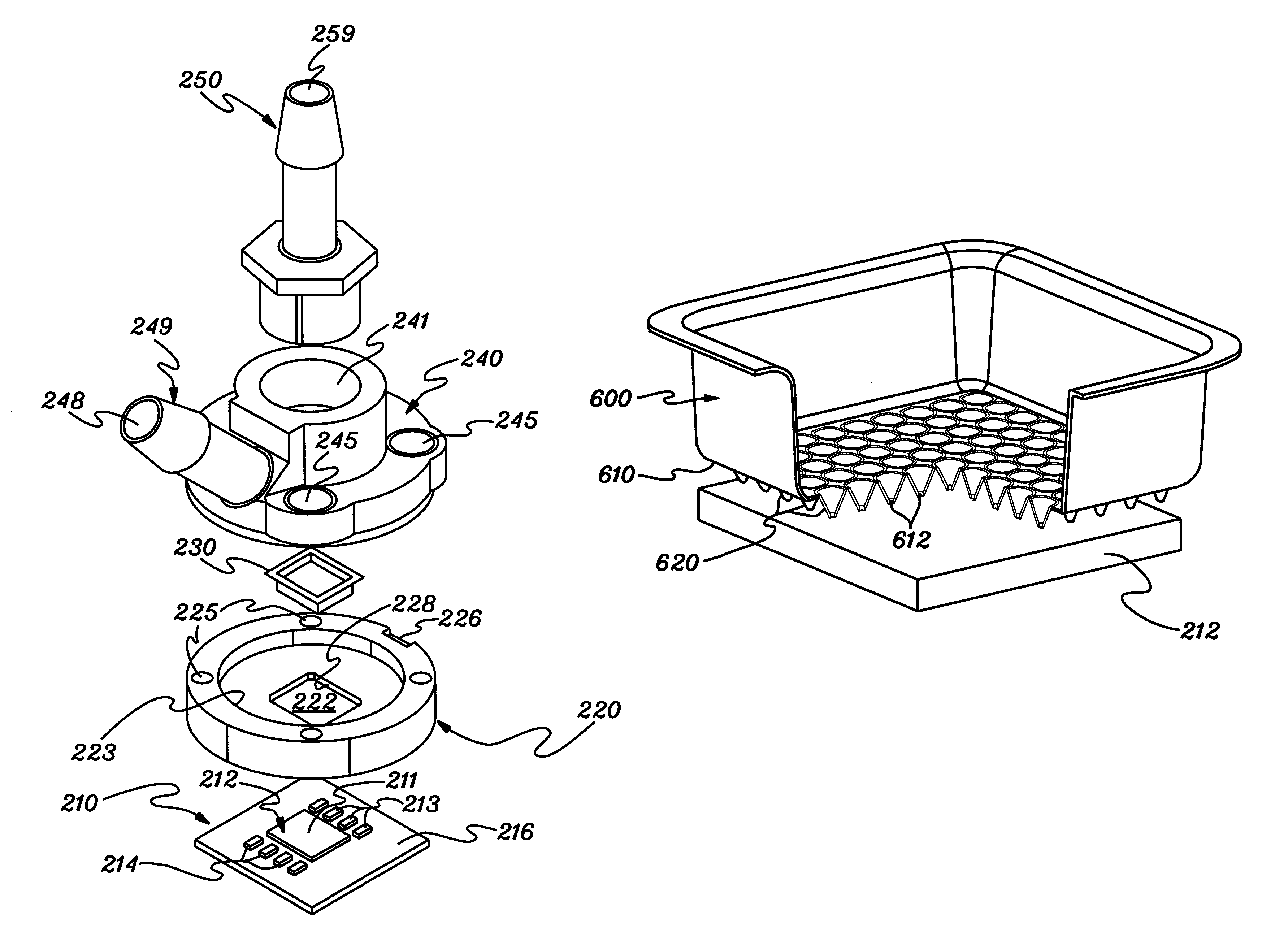
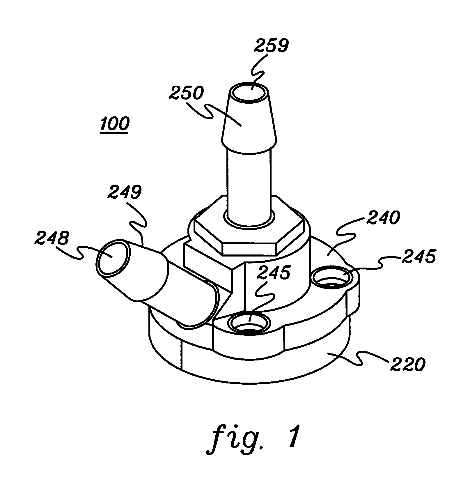
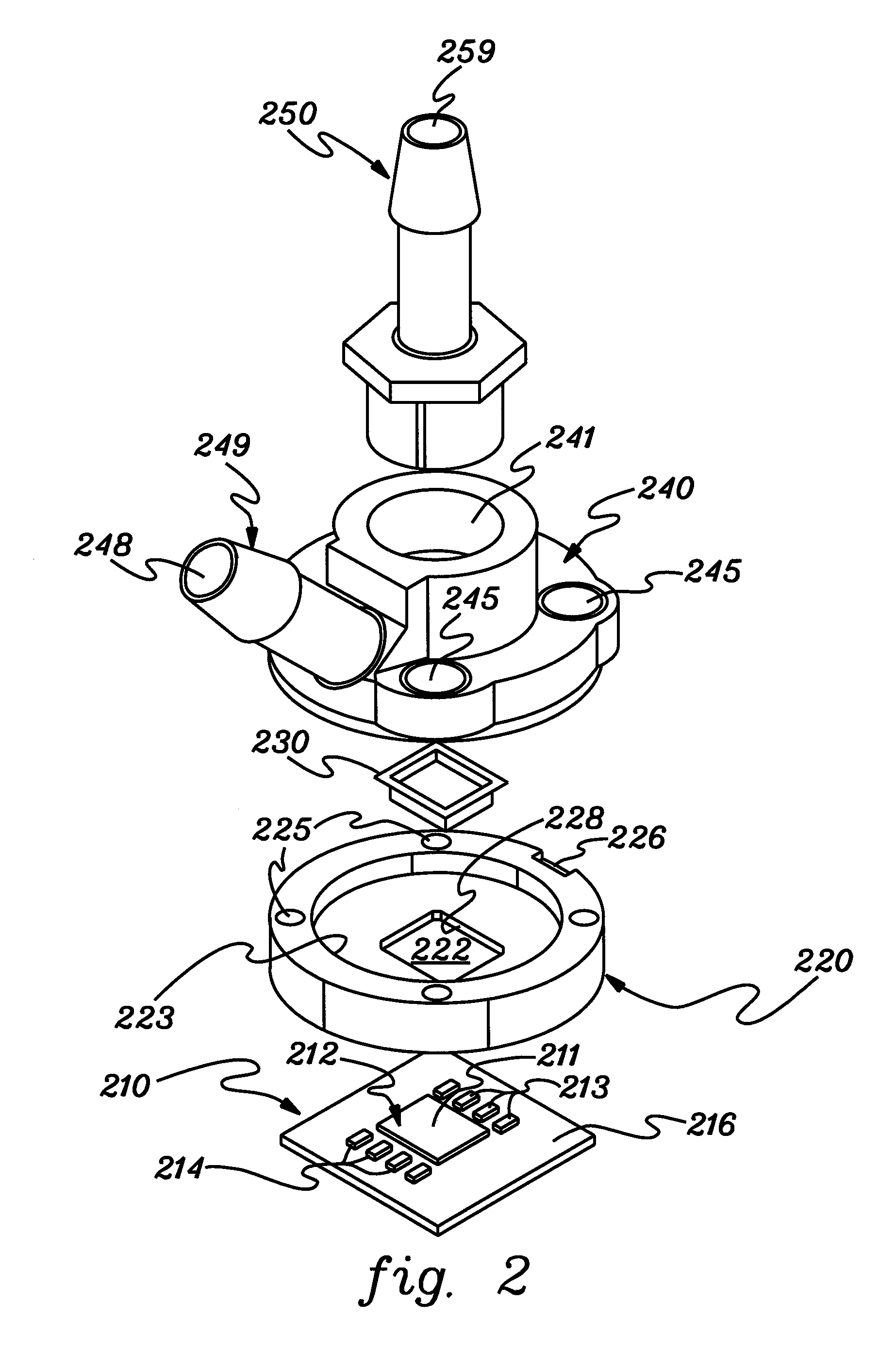
[0009]The shortcomings of the prior art are overcome and additional advantages are provided through the provision, in one aspect, of a cooling apparatus comprising a manifold structure and including a jet orifice plate for injecting coolant onto a surface to be cooled when the cooling apparatus is employed to cool at least one electronic component. The jet orifice plate, which includes a plurality of jet orifices for directing coolant at the at least one electronic component to be cooled, is configured with a plurality of jet orifice structures. Each jet orifice structure projects from a first surface of the jet orifice plate towards the surface to be cooled, and includes a respective jet orifice of the plurality of jet orifices. The plurality of jet orifice structures are spaced to define coolant effluent removal regions therebetween which facilitate removal of coolant effluent from over a center region of the at least one electronic component to a peripheral region thereof when the cooling apparatus is employed to cool the at least one electronic component, and thereby reduce pressure drop across the jet orifice plate.
[0010]In another aspect, a direct impingement cooling module is provided which includes a frame, a manifold and a jet orifice plate. The frame includes a frame opening configured to align over at least one electronic component to be cooled, and the manifold is disposed over the frame and has an inlet manifold opening and an outlet manifold opening. The inlet manifold opening is in fluid communication with a manifold inlet for supplying coolant, and the outlet manifold opening is in fluid communication with a manifold outlet for removing coolant effluent. The inlet manifold opening is aligned over the frame opening. The jet orifice plate is associated with the manifold and is aligned over the inlet manifold opening. The jet orifice plate includes a plurality of jet orifices for directing coolant at the at least one electronic component to be cooled. The jet orifice plate is a unitary plate configured with a plurality of jet orifice structures. Each jet orifice structure projects from a first surface of the jet orifice plate towards the at least one electronic component to be cooled. The plurality of jet orifice structures are spaced to define coolant effluent removal regions therebetween which facilitate removal of coolant effluent from over a center region of the at least one electronic component to a peripheral region thereof, for removal through the outlet manifold opening of the manifold, thereby reducing coolant pressure drop across the jet orifice plate.

Problems solved by technology

Despite these advantages, providing many electronic components in a small footprint can create device performance challenges.
Heat dissipation, if unresolved, can result in electronic and mechanical failures that will affect overall system performance, irrespective of the size of the environment.
Higher power dissipation in a smaller footprint leads to high heat loads and high heat fluxes.
Notwithstanding this, reliability constraints often dictate that operating temperature of the devices not exceed a known maximum value.
The existing art has struggled with designing high-performance cooling solutions that can efficiently remove this heat.
Unfortunately, providing greater airflow is not always possible.
Liquid cooling, however, is also limited by several factors.
Immersion cooled modules have the limitation that the critical heat flux of the dielectric coolant employed is relatively low, thereby limiting the acceptable chip heat flux.
Cold plate cooled modules have the limitation that intermediate materials and interfaces restrict the heat transfer capabilities of the module.

Method used


Image

  • Jet orifice plate with projecting jet orifice structures for direct impingement cooling apparatus
  • Jet orifice plate with projecting jet orifice structures for direct impingement cooling apparatus
  • Jet orifice plate with projecting jet orifice structures for direct impingement cooling apparatus

Examples


Embodiment Construction

[0025]As used herein “electronic component” comprises any heat generating electronic component of a computer system or other electronic system requiring cooling. In one example, the electronic component is or includes an integrated circuit chip, a semiconductor chip and / or any other electronic device requiring cooling. The term “cooled electronic module” includes any electronic module with direct or indirect cooling of an electronic component, with cooled single-chip modules and cooled multi-chip modules being examples of cooled electronic modules as described herein. In one embodiment, the cooled electronic module employs direct coolant impingement on the surface to be cooled, and is referred to herein as a “direct impingement cooling module”. The “surface to be cooled” refers to a surface of the electronic component itself, or to an exposed surface of a thermal cap, thermal spreader, passivation layer, or other surface in contact with the electronic component, and through which he...


PUM


Abstract

A cooling apparatus and a direct cooling impingement module are provided, along with a method of fabrication thereof. The cooling apparatus and direct impingement cooling module include a manifold structure and a jet orifice plate for injecting coolant onto a surface to be cooled. The jet orifice plate, which includes a plurality of jet orifices for directing coolant at the surface to be cooled, is a unitary plate configured with a plurality of jet orifice structures. Each jet orifice structure projects from a lower surface of the jet orifice plate towards the surface to be cooled, and includes a respective jet orifice. The jet orifice structures are spaced to define coolant effluent removal regions therebetween which facilitate removal of coolant effluent from over a center region of the electronic component being cooled to a peripheral region thereof, thereby reducing pressure drop across the jet orifice plate.

Description

CROSS REFERENCE TO RELATED PATENTS / APPLICATIONS[0001]This application contains subject matter which is related to the subject matter of the following patents / applications, each of which is assigned to the same assignee as this application and each of which is hereby incorporated herein by reference in its entirety:[0002]“Direct Liquid Jet Impingement Modules for High Heat Flux Electronics Packages”, Campbell et al., U.S. Ser. No. 11 / 427,380, filed Jun. 29, 2006; and[0003]“Fluidic Cooling Systems and Methods for Electronic Components”, Colgan et al., U.S. Pat. No. 7,079,393 B2, issued Jul. 18, 2006.TECHNICAL FIELD[0004]The present invention relates in general to heat transfer mechanisms, and more particularly, to cooling apparatuses, cooling modules and methods of fabrication thereof for removing heat generated by one or more electronic components. Still more particularly, the present invention relates to fluidic cooling apparatuses and methods for cooling one or more electronic comp...

Claims


Application Information

Patent Timeline
Patent Type & Authority Patents(United States)
IPC IPC(8): H05K7/20F28D15/00H01L23/24
CPCH01L23/4735Y10S165/908H01L2224/16H01L2924/00014H01L2924/00011H01L2224/0401
Inventor CAMPBELL, LEVI A.CHU, RICHARD C.ELLSWORTH, JR., MICHAEL J.IYENGAR, MADHUSUDAN K.SCHMIDT, ROGER R.SIMONS, ROBERT E.
Owner INT BUSINESS MASCH CORP
Learn More