
Eureka
For R&D, Eureka makes reading and utilizing patents & technical documents easy.
Eureka AIR
Designed for self-driven R&D workflows. Generate viable solutions, solve complex R&D challenges, empower your innovation with AI.

Eureka Materials
Designed for material experts only. Revolutionize your material R&D, from search, analyze, to developing new materials.

TechResearch
Generate reliable direction feasibility study reports for your R&D in just a few steps.

TechSeek
Discover and master advanced knowledge NOW. Basics, ideas, possibilities, all at once.

TechMind
As an expert in R&D Theories, TechMind can generates customized viable solutions instantly.

TechRisk
Analyze your overall solution with one click, know your potential R&D risks in advance.

TechMonitor
Get weekly tech updates, stay abreast of the latest tech innovations and key insights.
Self-folding polymer microparticles
- Summary
- Abstract
- Description
- Claims
- Application Information
AI Technical Summary
Benefits of technology
Problems solved by technology
Method used
Image

Examples
first embodiment
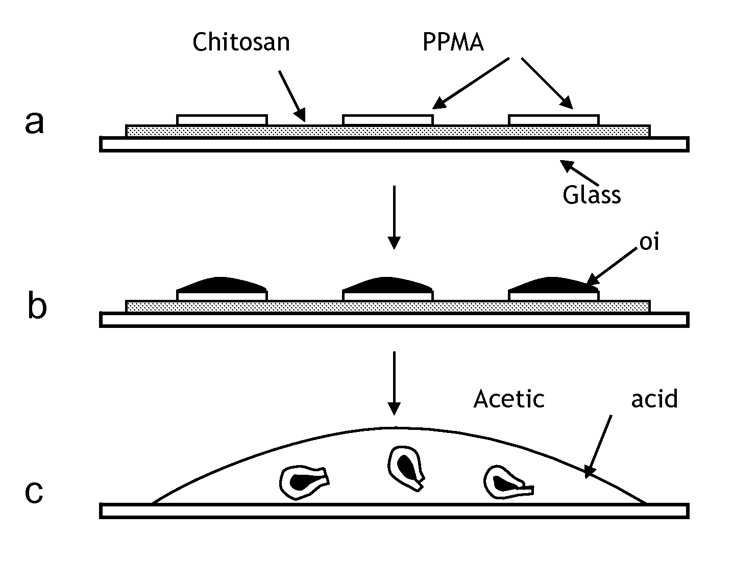
[0022]the method of the present invention is referred to as the “interfacial tension driven method.” With reference to FIGS. 1a-b, this method involves the following steps for creating self-folding polymer microparticles:
[0023]First, polymeric micropads are printed on a substrate that has been coated with a dissolvable “sacrificial” layer of material. In the exemplary embodiment of FIG. 1a, 40 μm-wide square poly (propyl methacrylate) (PPMA) micropads are printed on a chitosan-coated glass slide by a technique known as microContact Hot Printing (“μCHP”) which utilizes a poly (dimethyl siloxane) (PDMS) stamp. This technique is disclosed in U.S. patent application Ser. No. 10 / 656,661 filed on Sep. 5, 2003, entitled “Microfabrication of Polymer Microparticles,” the entire specification of which is hereby incorporated by reference.
[0024]Second, a thin layer of oil is applied to the substrate such that the oil only accumulates on the micropads. In an exemplary embodiment, food-grade soyb...
second embodiment
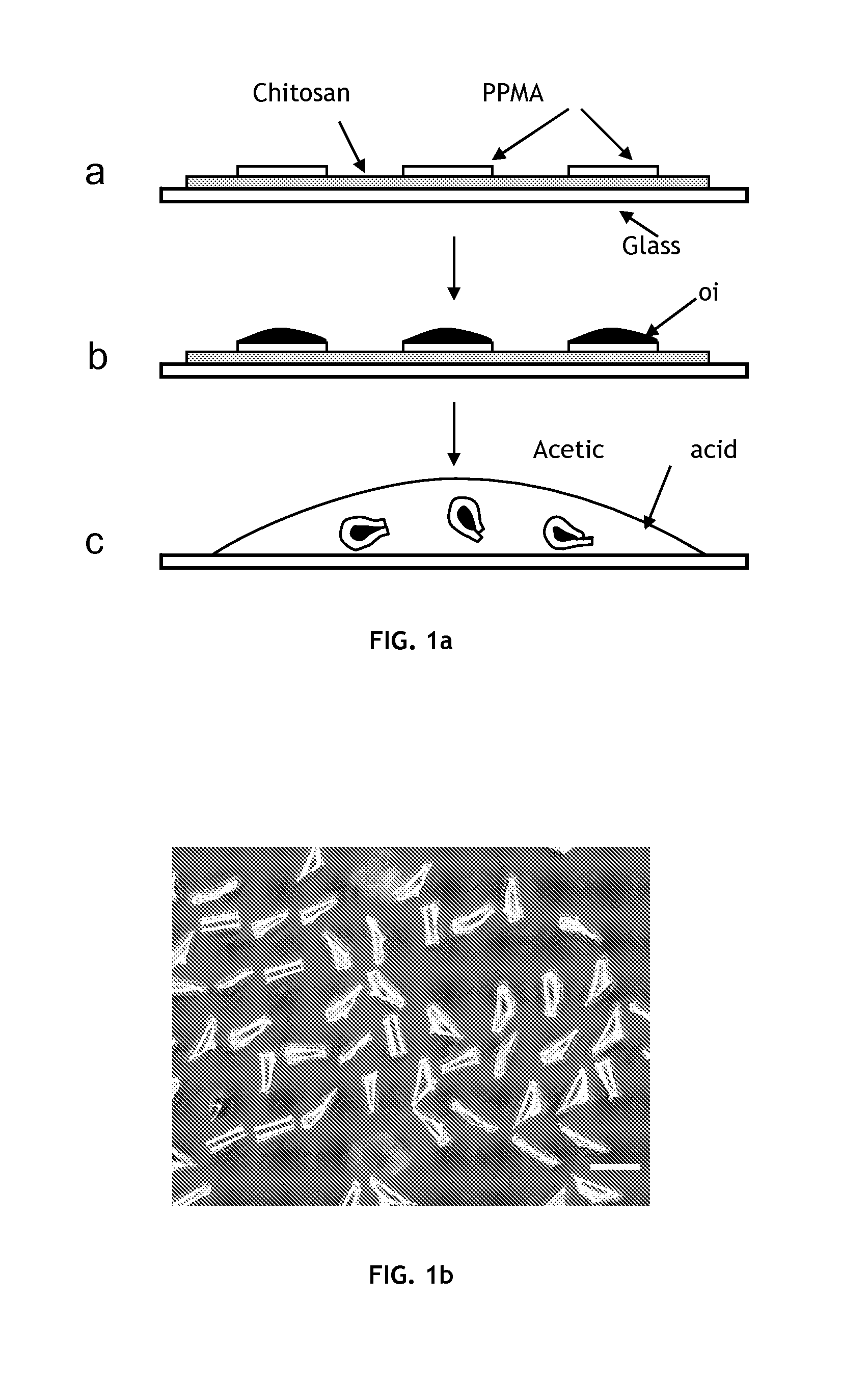
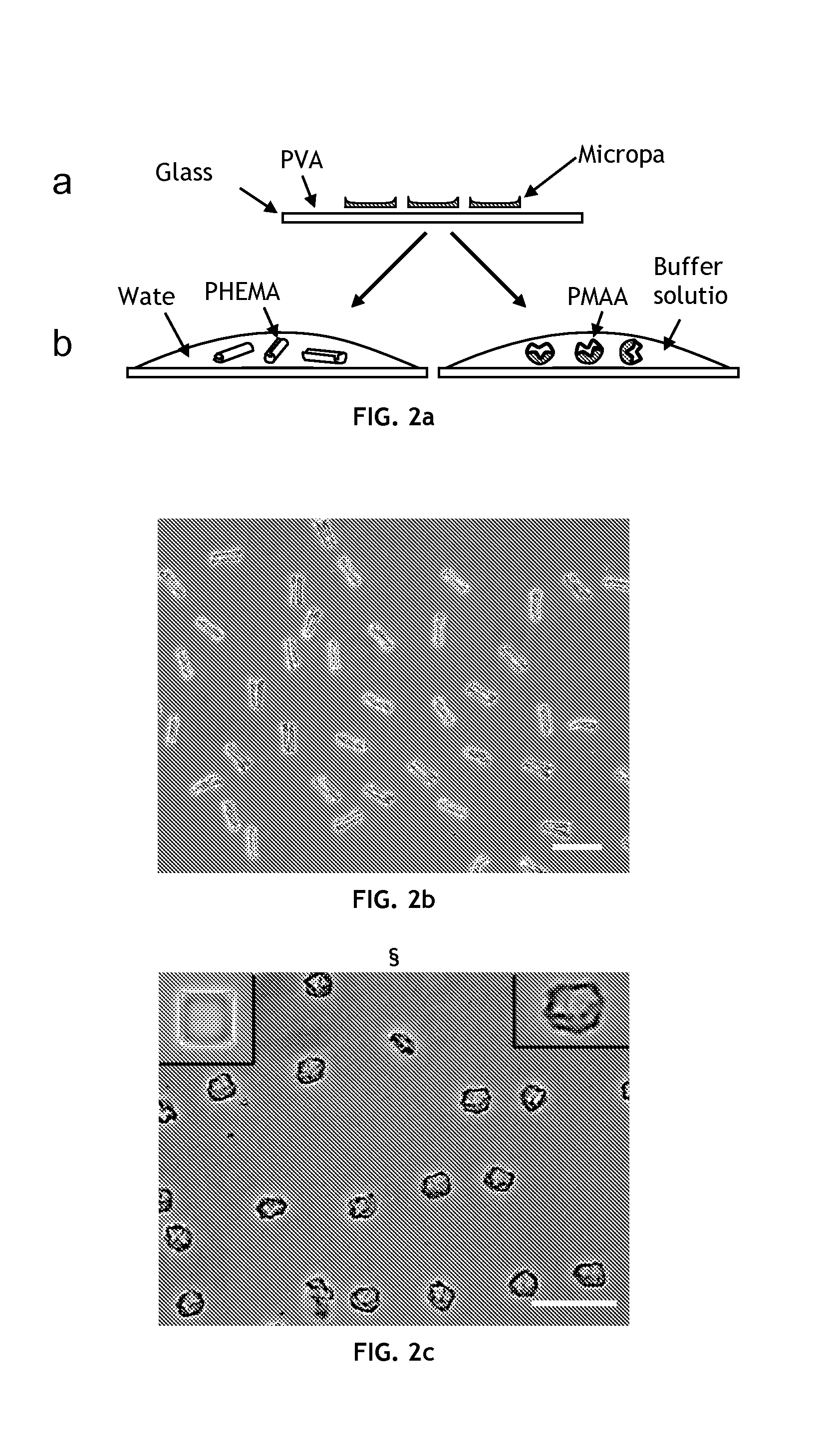
[0028]the method of the present invention is referred to as the “property gradient method.” This embodiment induces self-folding of hydrogel micropads to form three dimensional microstructures. With reference to FIGS. 2a-c, this method involves the following steps for creating self-folding polymer microparticles:
[0029]First, polymeric (i.e, hydrogel) micropads are printed on a substrate coated with a dissolvable or “sacrificial” layer using a PDMS stamp as described above. In the exemplary embodiment of FIGS. 2a-c, poly (hydroxyethyl methacrylate) (PHEMA) and poly (methacrylic acid) (PMAA) are used as the hydrogel component; however, other volume-changeable hydrogels are also compatible with this method. The PDMS stamp used for preparing PHEMA microstructures includes 40 μm-wide and 1.4 μm-deep square microwells separated by 10 μm-wide ridges. The PDMS stamp used for preparing the PMAA microstructures includes 30 μm-wide and 1.1 μm-deep square microwells separated by 20 μm-wide ridg...
third embodiment
[0036]the method of the present invention is referred to as the “bilayer method.” With reference to FIGS. 3a-b, this method involves the following steps for creating self-folding polymer microparticles:
[0037]First, bilayer polymeric micropads are printed on a substrate coated with a dissolvable or “sacrificial” layer using a PDMS stamp as described in U.S. patent application Ser. No. 10 / 656,661. Second, a solvent is added to dissolve the sacrificial layer and release the micropads into solution. The released micropads curl spontaneously or curl in the presence of a certain stimulus such as a change in pH. In the exemplary embodiment of FIGS. 3a-b, 40 μm-wide square microparticles were fabricated using a PMAA / PLGA (polylactic-co-glycolic acid) bilayer. FIG. 3b is an optical micrograph of the curled PMAA / PLGA bilayer microstructures in water (scale bar=100 μm).
[0038]The spontaneous curling of the microparticles in this embodiment is likely due to a differential volume change of the tw...
PUM
 Abstract
Description
Claims
Application Information
 - R&D Engineer
- R&D Manager
- IP Professional
- Industry Leading Data Capabilities
- Powerful AI technology
- Patent DNA Extraction
Browse by: Latest US Patents, China's latest patents, Technical Efficacy Thesaurus, Application Domain, Technology Topic, Popular Technical Reports.
© 2024 PatSnap. All rights reserved.Legal|Privacy policy|Modern Slavery Act Transparency Statement|Sitemap|About US| Contact US: help@patsnap.com