Optical spectrum analyzer

a spectrum analyzer and optical technology, applied in the field of optical spectrum analyzers, can solve the problems of disc plate b>6/b> being liable to be changed in structure, unable to increase wavelength in a wide range in principle, and difficult to obtain narrow band characteristics, etc., to achieve high wavelength accuracy and speed. high

Inactive Publication Date: 2008-04-29
ANRITSU CORP
View PDF11 Cites 3 Cited by
  • Summary
  • Abstract
  • Description
  • Claims
  • Application Information

AI Technical Summary

Benefits of technology

[0029]To solve the problems of the prior arts as described above, an object of the present invention is to provide an optical spectrum analyzer that can continuously measure to-be-measured light in a wide wavelength range at high speed while maintaining high wavelength accuracy by measuring the to-be-measured light accompanied with calibration processing for correcting wavelength information based on spectrum data obtained by causing reference light whose wavelength is known to be incident on a tunable wavelength filter at all times together with the to-be-measured light.
[0124]In the optical spectrum analyzers according to the first to twentieth aspects of the present invention configured as described above, the to-be-measured light is measured accompanied with the calibration processing for correcting the wavelength information of the spectrum data of the to-be-measured light based on the spectrum data of the reference light that is obtained by causing the reference light having the known wavelength to be incident on the tunable wavelength filter at all times together with the to-be-measured light. As a result, since the to-be-measured light can be continuously measured in the wide wavelength range at the high speed while maintaining the high wavelength accuracy, there are obtained such advantages that spectrum data of the to-be-measured light having the high wavelength accuracy can be continuously obtained even if the optical spectrum analyzer is installed in a place in which an environment intensely changes.
[0125]Further, the optical spectrum analyzer according to the twenty-first aspect of the present invention has such advantages that control can be easily carried out and the wavelength can be changed in a wide range at high speed because the diffraction grating and the turning mirror having the so-called MEMS structure are used as the tunable wavelength filter, in addition to the advantages of the optical spectrum analyzers according to the first to twentieth aspects of the present invention.

Problems solved by technology

However, the optical spectrum analyzer using the Fairy-Perot filter as the tunable wavelength filter has a problem in that a wavelength cannot be increased in a wide range in principle.
. . , thereby it is difficult to obtain narrow band characteristics.
Further, a problem also arises in that the attitude of the disc plate 6 is liable to be changed in structure by a change of temperature and humidity and accuracy of an outgoing wavelength is deteriorated thereby.
However, when the optical spectrum analyzer is used in a place in which an environment is intensely changed, an optical system is changed by the change of the environment, from which a problem may arise in that the accuracy of wavelength of the obtained spectrum data is greatly deteriorated.
Accordingly, the optical spectrum analyzer itself must be calibrated frequently, from which a problem arises in that it is difficult to continuously measure to-be-measured light that is to be continuously measured intrinsically.

Method used


Image

  • Optical spectrum analyzer
  • Optical spectrum analyzer
  • Optical spectrum analyzer

Examples


first embodiment

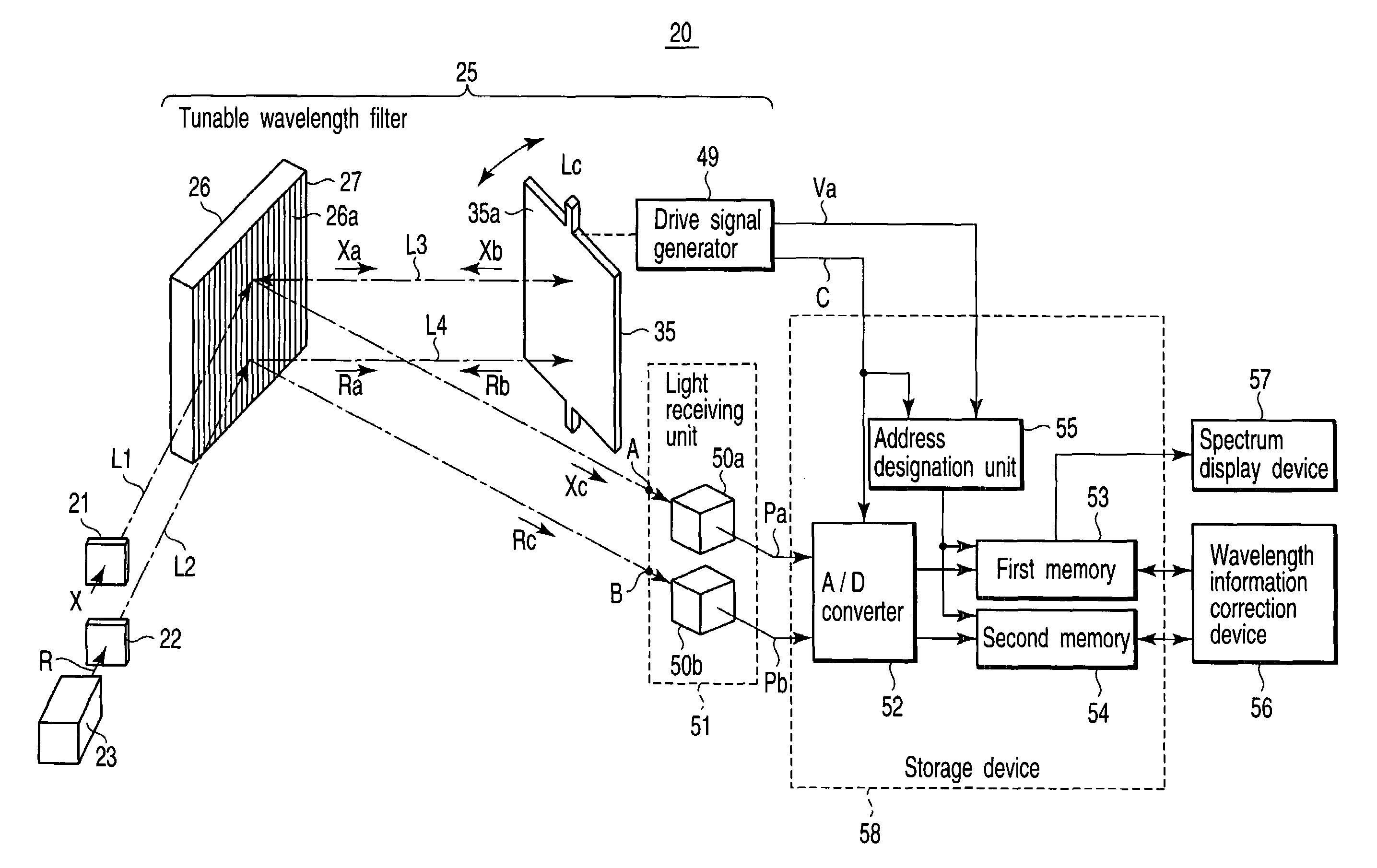
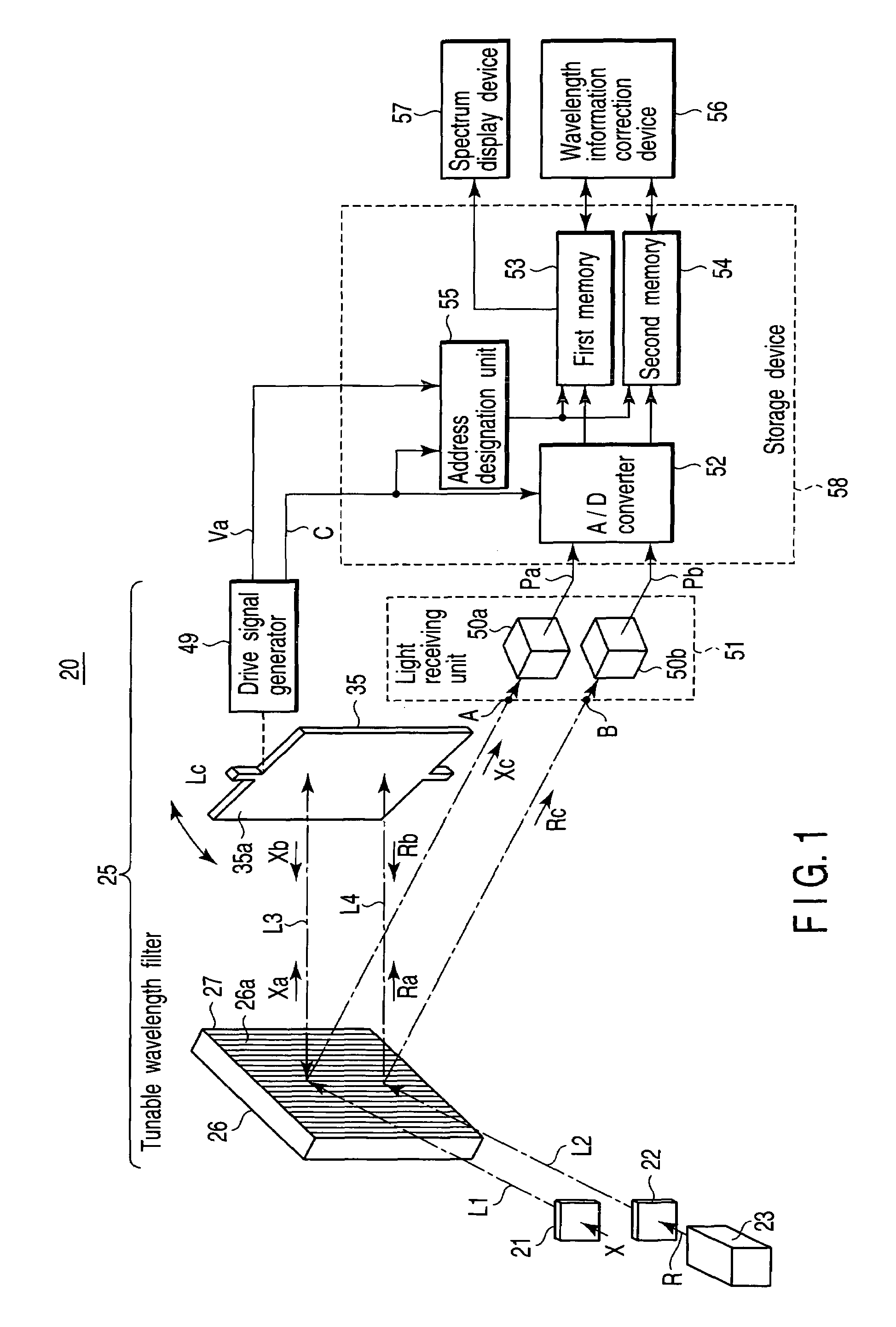
[0148]FIG. 1 is a block diagram shown to explain an overall configuration of an optical spectrum analyzer 20 according to a first embodiment of the present invention.

[0149]That is, the optical spectrum analyzer of the present invention basically includes a tunable wavelength filter 25, a reference light source 23, light incident devices 21 and 22, a light receiving device 51, a storage device 58, and a correction device 56. The tunable wavelength filter 25 causes wavelength components contained in incident light to selectively exit therefrom as well as changes the selected wavelength as time passes. The reference light source 23 radiates reference light R whose wavelength in which light intensity is maximized or minimized is known. The light incident devices 21 and 22 cause to-be-measured light X to be incident on the tunable wavelength filter 25 along a first optical axis L1 and at the same time cause the reference light R from the reference light source 23 to be incident on the tu...

second embodiment

[0221]FIG. 11 is a block diagram shown to explain a configuration of an optical spectrum analyzer 60 according to a second embodiment of the present invention.

[0222]Note that, in FIG. 11, the portions arranged similar to those of the optical spectrum analyzer 20 according to the first embodiment described above are denoted by the same reference numerals as those in FIG. 1 and the explanation thereof is omitted.

[0223]In the optical spectrum analyzer 20 according to the first embodiment of the invention described above, the reference light R and the to-be-measured light X are caused to be incident on the single diffraction grating 26 of the tunable wavelength filter 25.

[0224]However, the tunable wavelength filter 25 may be configured by using two diffraction gratings 26A and 26B as in the optical spectrum analyzer 60 according to the second embodiment of the invention shown in FIG. 11.

[0225]The first diffraction grating 26A receives to-be-measured light X incident thereon from a first...

third embodiment

[0232]FIG. 12 is a block diagram shown to explain a configuration of an optical spectrum analyzer 70 according to a third embodiment of the present invention.

[0233]Note that, in FIG. 12, the portions configured similar to those of the optical spectrum analyzer 60 according to the second embodiment described above are denoted by the same reference numerals as those in FIGS. 1 and 11 and the explanation thereof is omitted.

[0234]When the two diffraction gratings 26A and 26B are used as in the optical spectrum analyzer 60 according to the second embodiment of the invention, the height of the turning mirror 35 can be reduced in an axial direction.

[0235]FIG. 12 shows a configuration example of the optical spectrum analyzer 70 in which two diffraction gratings 26A and 26B are arranged in plane symmetry.

[0236]The first diffraction grating 26A receives to-be-measured light X incident thereon from a first light incident device 21 at a predetermined angle on a diffraction surface 26a, causes d...


PUM


Abstract

An optical spectrum analyzer measures to-be-measured light while carrying out calibration processing for correcting wavelength information of spectrum data of the to-be-measured light by a wavelength information correction device through a storage device based on the spectrum data of reference light that is obtained by causing the reference light whose wavelength is known to be incident on a tunable wavelength filter from light incident devices at all times together with the to-be-measured light. Since the optical spectrum analyzer can continuously measure the to-be-measured light in a wide wavelength range at high speed while maintaining high wavelength accuracy, it can continuously obtain the spectrum data of the to-be-measured light with high wavelength accuracy even if it is installed in a place in which an environment intensely changes.

Description

CROSS-REFERENCE TO RELATED APPLICATIONS[0001]This application is based upon and claims the benefit of priority from prior Japanese Patent Application No. 2005-022068, filed Jan. 28, 2005, the entire contents of which are incorporated herein by reference.BACKGROUND OF THE INVENTION[0002]1. Field of the Invention[0003]The present invention relates to an optical spectrum analyzer, and more particularly, to an optical spectrum analyzer that employs a technology for improving wavelength accuracy of spectrum characteristics of light when the spectrum characteristics are determined by using a tunable wavelength filter.[0004]2. Description of the Related Art[0005]Optical spectrum analyzers for determining spectrum characteristics of light determine a relation between wavelength and intensity as spectrum characteristics of to-be-measured light, that is, spectrum data by detecting intensity of light that is caused to exit from a tunable wavelength filter on which the to-be-measured light is i...

Claims


Application Information

Patent Timeline
Patent Type & Authority Patents(United States)
IPC IPC(8): G01J3/18
CPCG01J3/02G01J3/0202G01J3/021G01J3/0243G01J3/1804G01J3/28G01J2003/2866
Inventor TAKAHASHI, YOSHIFUMISAITOH, TAKANORINAKAMURA, KENICHI
Owner ANRITSU CORP
Why Eureka
Try Eureka