Crosstalk reduction in a backplane employing low-skew clock distribution

a backplane and clock distribution technology, applied in the field of channel crosstalk reduction, can solve the problems of common-mode imbalance, coupling of signals in the two channels, and p-n common-mode imbalance, and achieve the effect of reducing near-end crosstalk and reducing far-end crosstalk

Inactive Publication Date: 2008-04-29
AVAGO TECH WIRELESS IP SINGAPORE PTE
View PDF3 Cites 5 Cited by
  • Summary
  • Abstract
  • Description
  • Claims
  • Application Information

AI Technical Summary

Problems solved by technology

The majority of FEXT that a channel experiences is due to common-mode imbalance.
That common-mode imbalance is directly related to positive-to-negative (P-N) skew (misalignment) between the signals in the differential pair of the module's transmit portion of the channel.
This placement may cause i) coupling of signals in the two channels to occur and ii) P-N common-mode imbalance to occur.
In addition, crosstalk effects might not limit package size, and package parasitic terms might limit effectiveness of crosstalk reduction circuits.
Such precise control is severely limited when attempting to create low skew (<20 ps) control loops between separately packaged interfaces.
Due to the larger physical size of an individually packaged part, crosstalk control of the prior art might not provide noticeable improvements in background noise.
However, latency in the various clock signals may yield differences in timing between events on a given system-on-chip (SOC) implementation.
However, timing inaccuracy occurs between the dividers, which timing inaccuracy is a function of the depth of memory (i.e., number of flip-flops) of a divider circuit and propagation delay differences inherent in electrical wiring or transmission lines.
The most significant source of error is the accrual of latency differences due to differences in the stored state of the divider circuit outside of the PLL feedback circuit.
As system speeds and circuit density increases, these small latency differences may affect SOC ASIC performance.
An example of potential performance limitation is substrate noise.
The timing latency differences between sections of the ASIC served by the low-speed distribution network might result in substrate noise that occurs with limited predictability.
Thus, SOC events are timed with an unpredictability based on the state differences between the divider circuits.
An SOC scheduler of a prior art system might be unable to predict when activity-induced substrate noise will begin and may be scheduling events that ultimately lead to i) excessive jitter of the ground potential and ii) system meta-stability.

Method used


Image

  • Crosstalk reduction in a backplane employing low-skew clock distribution
  • Crosstalk reduction in a backplane employing low-skew clock distribution
  • Crosstalk reduction in a backplane employing low-skew clock distribution

Examples


Embodiment Construction

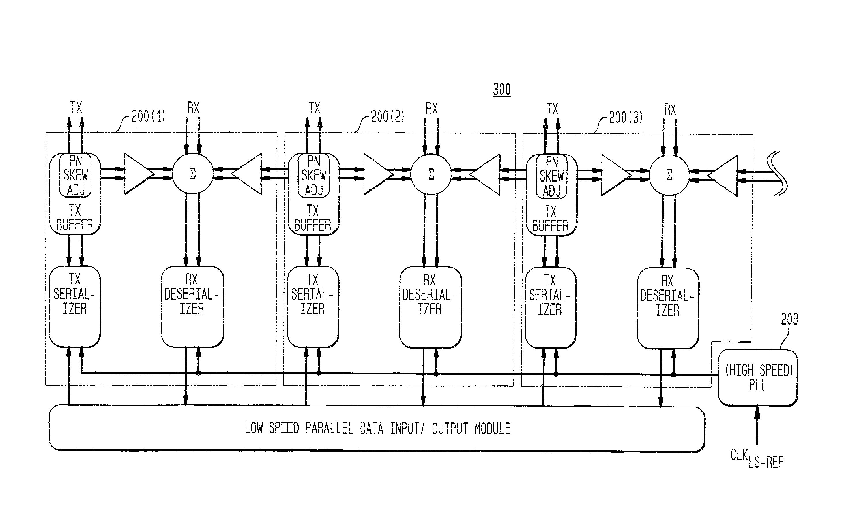
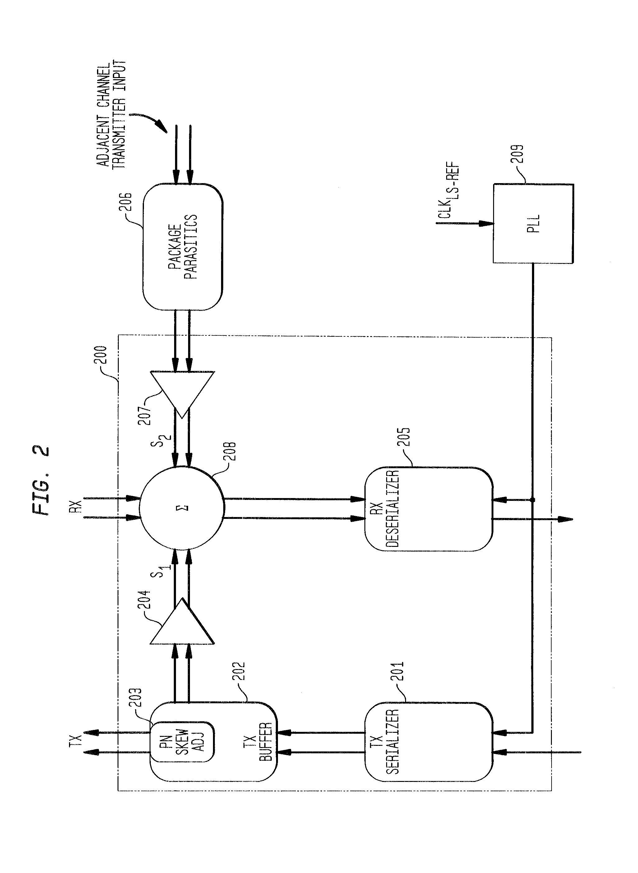
[0023]FIG. 2 shows a channel unit 200 employing crosstalk reduction in accordance with an exemplary embodiment of the present invention. In the transmit portion, channel unit 200 comprises transmit (TX) serializer 201, TX buffer 202 including positive-to-negative skew adjuster (PN skew adj) 203, and gain adjuster 204. In the receive portion, channel unit 200 comprises combiner 208, receive (RX) deserializer 205, and gain adjuster 207. Gain adjusters 204 and 207 may be implemented with amplifiers. Channel unit 200 is coupled to phase-locked loop (PLL) 209 and may receive signals from an adjacent channel transmitter. Signals from the adjacent channel transmitter may be modified when passing through the impedance of the backplane or similar structure (shown as package parasitics 206).

[0024]Transmit portion (TX) of channel unit 200 may be coupled to a receiver of a far-end channel unit, while receive portion (RX) of channel unit 200 may be coupled to a transmitter of the far-end channel...


PUM


Abstract

A system for a backplane that employs i) an adjustment of positive-to-negative (P-N) driver skew of a transmit signal of a relatively high-speed differential driver to reduce far-end crosstalk, ii) a high-speed differential subtraction circuit combining a gain-adjusted replica of at least one transmit signal with a received signal to reduce near-end crosstalk, and iii) a phase-locked loop (PLL) synchronization circuit to align timing events between a set of near-end and far-end high-speed interfaces.

Description

CROSS-REFERENCE TO RELATED APPLICATIONS[0001]This application claims the benefit of the filing date of U.S. provisional application No. 60 / 514,427, filed on Oct. 24, 2003.BACKGROUND OF THE INVENTION[0002]1. Field of the Invention[0003]The present invention relates to transfer of signals through channels of a backplane, and, more specifically, to reduction of crosstalk between the channels.[0004]2. Description of the Related Art[0005]A terminal transferring signals in channels between circuit boards, a circuit board transferring signals in channels between circuit components, and an application specific integrated circuit (ASIC) transferring signals in channels between circuit modules are examples of typical communication applications. These communication applications may employ a backplane to couple the circuit boards / components / modules. For these communication applications, a backplane that has groups of transmit and receive channels may have the channels physically located very cl...

Claims


Application Information

Patent Timeline
Patent Type & Authority Patents(United States)
IPC IPC(8): H04J1/12G06F13/40H04B3/32H05K1/02
CPCG06F13/409H04B3/32H05K1/0216
Inventor ABEL, CHRISTOPHER J.ANIDJAR, JOSEPHCHLIPALA, JAMES D.DUGGAL, ABHISHEKLATURELL, DONALD R.
Owner AVAGO TECH WIRELESS IP SINGAPORE PTE
Why Eureka
Try Eureka