Modulator bias control

a technology of bias control and optical modulator, applied in the field of bias control of optical modulators, can solve the problems that the method of controlling the bias point of an optical modulator is believed to fail to effectively maintain the optimum bias point, and achieve the effect of minimising adverse consequences

Inactive Publication Date: 2008-05-06
PHOTONICSYST
View PDF27 Cites 47 Cited by
  • Summary
  • Abstract
  • Description
  • Claims
  • Application Information

AI Technical Summary

Benefits of technology

[0010]Bias controllers and bias control methods according to the invention may be advantageous in that they can allow for straightforward implementations that maintain lock on a bias point when a large modulation signal—on the order of 100% modulation depth (Vπ for an MZ or Vs for an EA modulator)—is applied to the modulator. This is particularly advantageous in telecommunications systems because system designers can obtain the best bit error rate when the amplitude of the m...

Problems solved by technology

Since it appears that there has not been a commercially viable solution using the former approach, the use of bias controllers that implement the latter approach has become the standard method for dealing with the modulator drift problem.
These pri...

Method used


Image

  • Modulator bias control
  • Modulator bias control
  • Modulator bias control

Examples


Embodiment Construction

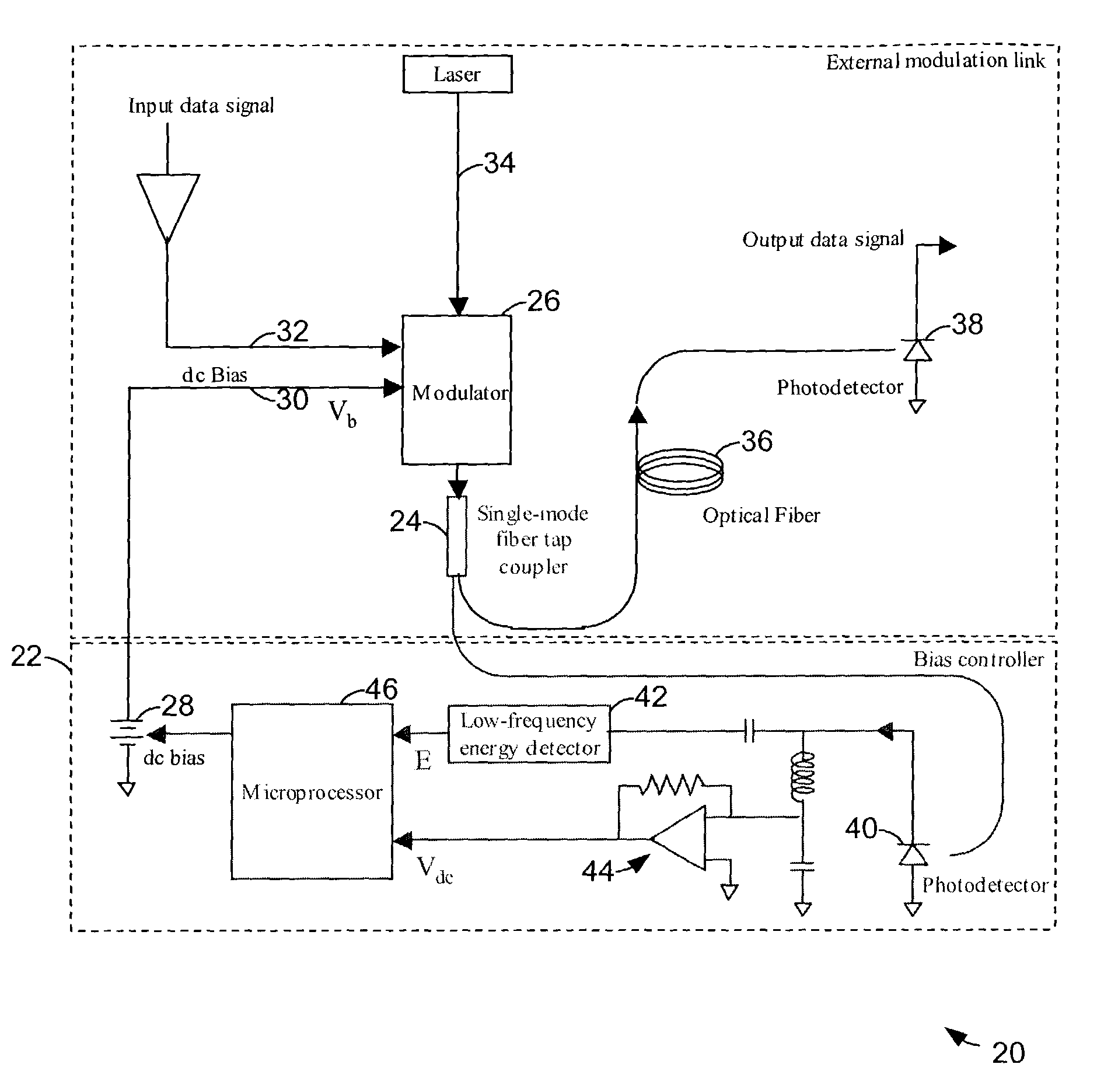
[0024]Referring to FIG. 6, a modulation bias control system 20 according to one aspect of the invention can include a bias controller 22 having an input operatively connected to one of the outputs of a single-mode fiber tap coupler 24 at the output of a modulator 26. The bias controller has an output operatively connected to an adjustable direct current (DC) bias source 28. An output 30 of the bias source is operatively connected to a bias input of the modulator, which is also operatively connected to a data signal input 32 and an output of a source of optical energy 34, such as a laser. The second output of the coupler can be operatively connected via a communications channel, such as an optical fiber 36, to a remote destination, such as a remote photodetector 38.

[0025]The bias controller can include a photodetector 40 followed by a low frequency energy detector 42 and an optional low-pass filter 44 (to provide information about the average optical power out of the modulator, which...


PUM


Abstract

Approaches to bias control are disclosed for an optical modulator that modulates an optical carrier with a data input signal. In one embodiment an electrical bias input signal provided to the modulator is adjusted based on a characteristic of the data input signal detected from the modulated optical output signal. Another embodiment injects an additive dither signal into an optical modulator receiving a data input signal having a modulation depth of at least on the order of 50%. These embodiments can obtain and maintain a correct bias point on a modulator's transfer function curve when the modulation signal has a modulation depth on the order of 100%.

Description

FIELD OF THE INVENTION[0001]This invention relates to the bias control of optical modulators.BACKGROUND OF THE INVENTION[0002]One method for imposing an electrical signal onto an optical carrier is to use an external modulator. Examples of external modulators presently in use include Mach-Zehnder (MZ) and electro-absorption (EA) types. In most cases, pyroelectric, photorefractive and photoconductive effects in the device material of a modulator (often lithium niobate, or a semiconductor like GaAs, or an electro-optic polymer) can cause its output power-vs-input voltage characteristic (i.e., its transfer function) to change or “drift,” over time or temperature. The result of drift is that a specific DC bias voltage (or even 0 Volts) may, for example, yield a minimum point on the transfer function curve at one time, but yield a different point on the curve at a later time and / or at a different temperature. This situation is illustrated in FIG. 1 for a digital application of a Mach-Zeh...

Claims


Application Information

Patent Timeline
IPC IPC(8): G02B26/00
CPCG02F1/0123G02F1/225G02F2001/0157G02F2001/212G02F2203/20G02F1/0157G02F1/212
Inventor COX, CHARLES H.ACKERMAN, EDWARD I.
Owner PHOTONICSYST
Why Eureka
Try Eureka